
Controller Link Units Operation Manual


264
Data Link I/O Response Time Section 8-3
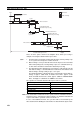
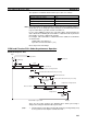
2. Data exchange occurs just after the PLC at node #1 passes the token that
makes it the polling node, causing a delay of up to one communications cy-
cle time before the data is transferred in data link processing.
3. At node #7, data from the previous data exchange is still being transferred,
causing a delay of up to one cycle before the input is read into the PLC.
4. The data transferred in data link processing arrives at the PLC at node #7
after data exchange, so the data will not be read into the PLC until the next
data exchange, causing a delay of up to one peripheral servicing interval.
Up to 3,700 words can be transferred in a single data exchange, so a delay
of another peripheral servicing interval will occur if more than 3,700 words
are being transferred.
5. The data is received after the PLC at node #7 has executed the instruction,
causing a delay of up to one cycle time.
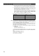
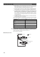
Assume that the peripheral servicing interval of the PLCs at nodes #1 and #7
is 10 ms. The equation for maximum data link I/O response time is as follows:
Note If the total number of data link words is greater than the maximum number of
words that can be exchanged per data exchange, the maximum data link I/O
response time will be cycle time of PLC at node #7
× 3.
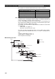
Noise may increase I/O delays.
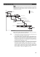
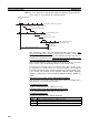
Minimum Response Time
Input ON delay 1.5 ms
Cycle time of PLC at node #1 × 215 ms × 2
Peripheral servicing interval of PLC at
node #1
10 ms
Communications cycle time × 39.9 ms × 3
Peripheral servicing interval of PLC at
node #7 × 2
10 ms × 2
PLC cycle time at node #7 × 2 (See note.) 20 ms × 2 (See note.)
Output ON delay 15 ms
Total (data link I/O response time) 146.2 ms
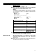
Input
Input device
Input ON delay
1 cycle
I/O refresh
PLC at node #1
PLC at node #7
Peripheral servicing interval
Peripheral servicing interval
Output device
Output
ON delay
Data link I/O res
p
onse time
Program ◆
◆ Program
Data link transmission
Data processing time
Data processing time