
Controller Link Units Operation Manual


351
Memory Areas Appendix B
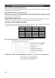
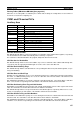
DM Area: CS/CJ CPU Bus Unit Area
The CS/CJ CPU Bus Unit Area (DM Area) is allocated to CS/CJ CPU Bus Units according to the unit numbers
assigned to them, as shown below. Each Unit is allocated 100 words, of which 10 words are used. In the Con-
troller Link Unit this area is called the DM Area.
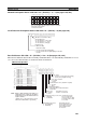
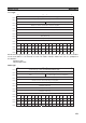
Software Switches (DM30000 + 100 × Unit No.) (See pages 145, 243, 249, 318.)
Unit no. Words Unit no. Words
0 DM30000 to
DM30009
8 DM30800 to
DM30809
1 DM30100 to
DM30109
9 DM30900 to
DM30909
2 DM30200 to
DM30209
10 DM31000 to
DM31009
3 DM30300 to
DM30309
11 DM31100 to
DM31109
4 DM30400 to
DM30409
12 DM31200 to
DM31209
5 DM30500 to
DM30509
13 DM31300 to
DM31309
6 DM30600 to
DM30609
14 DM31400 to
DM31409
7 DM30700 to
DM30709
15 DM31500 to
DM31509
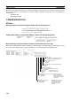
Data link mode
000: Manual
001: Automatic, equality layout
15 14 13 12 11 10 9 8 7 6 5 4 3 2 1 0
0 000 000
CS1 CPU Bus Unit PLC Setup Initialization (See note 1.)
0: Do not initialize CS1 CPU Bus Unit PLC Setup
1: Initialize CS1 CPU Bus Unit PLC Setup
Polling node/polled node bit
0: Polling node
1: Polled node
0
Data Link Start Bit
Start: Changed from OFF to ON or set to ON
when power is turned ON.
Stop: Changed from ON to OFF.
0: Always set to 0.
Note 1: Initializes the network parameters registered in the CS1 CPU Bus Unit PLC Setup Area on the CPU Unit
and clears the data link tables.
2: Be sure to set the bit in the DM Area's (CPU Bus Unit Area's) software switches (D30000 + 100 × unit
number) described as "always set to 0" to 0. Not doing so may result in the data link not starting properly.
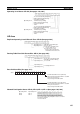
If a data link is started with bit 7 of the software switches set to 1, the data link status will be stored in a
format different to the one described in this manual (when using CS-series or CJ-series Controller Link Units).
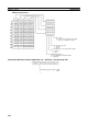
Wired Network 62 Node
Enable Bit
0: 32 nodes max.
1: 62 nodes max.
101: Automatic, 1:N allocation
Data link status
storage format
0: 8-bit format
1: 4-bit format