
Controller Link Units Operation Manual


356
Memory Areas Appendix B
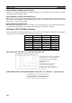
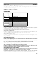
Communications Controller Hardware Error, EEPROM Error: AR 11, AR 15 (See page 299.)
Service Time: AR 16, AR 17 (See page 299.)
Operating Level Connection Status, Inconsistent Network Parameters: AR 24 (See page 299.)
DM Parameter Area
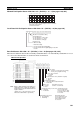
Software Switches: DM 6400 and DM 6420 (See pages 145, 243, 249, 318.)
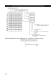
Parameters for Automatically Setting Data Links: DM 6400 to DM 6409, DM 6420 to DM 6429
(See page 145.)
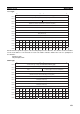
Operating level 0
AR 11
Operating level 1
AR 15
1: Communications controller hardware error
1: EEPROM error
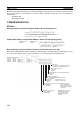
Operating level 0
AR 16
Operating level 1
AR 17
The service time for each PLC cycle is calculated by the PLC
and displayed in 0.1-ms units in 4-digit BCD.
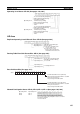
Operating level 1
Operating level 0
1: Network parameters do not match
1: Connecting to the operating level
Operating level 1
Operating level 0
Data link mode
00: Manual
01: Automatic
15 14 13 12 11 10 9 8 765 4 3 2 1 0
0 000000 0000
EEPROM Clear Bit 0: Do not clear EEPROM
1: Clear EEPROM
Routing table enabled/disabled
1: Enabled
0: Disabled
Polling node/polled node bit
0: Polling node
1: Polled node
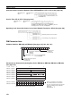
Area 1 data link start word (BCD)
Area 1 type
Number of send words per node of area 1 (BCD)
Rightmost 4 digits of data link start word of area 2 (DM area) (BCD)
Leftmost digit of data link start word of area
2 (BCD)
First data link status word (BCD)
BCD: Set the value as binary-coded decimal.
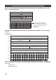
Nodes to participate in the data links
The numbers indicate node numbers.
The value assigned indicates whether the
node is to participate in the data links.
Participate: 1
Not participate: 0
15 8 7
0
15 14 13 12 11 10 9 8 7 6 5 4 3 2 10
16
15141312111098765432
1
DM 6401 DM6421
DM 6402 DM6422
DM 6403 DM6423
DM 6404 DM6424
DM 6405 DM6425
DM 6406 DM6426
DM 6407 DM6427
DM 6408 DM6428
32 31 30 29 28 27 26 25 24 23 22 21 20 19 18 17
DM 6409 DM 6429
Area 2 type
Number of send words per node of area 2 (BCD)
00
Level 0 Level 1