
Controller Link Units Operation Manual

57
Component Names and Functions Section 3-1
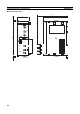
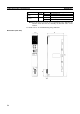
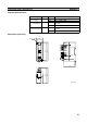
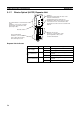
Dimensions (Unit: mm)
3-1-8 Wire-to-Optical (GI) Repeater Unit
75.6
73.3
8
59
Two, 4.5 dia.
30
90
21
81
(Unit: mm)
O
N
1
2
O
N
1
2
DC24V
INPUT
SL1
SL2
T/R2
T/R1
PWR
CS1W-RPT03
BD L
SHLD
BD H
TER SW
ON
ON
SW1
BAUD
RATE
1
2
+
−
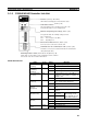
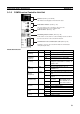
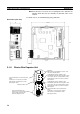
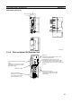
SL1 Terminal Block for Communications
Cable
Terminals to connect to the Controller
Link Network communications cable
(twisted-pair cable).
Baud rate switch
Power Terminal Block
Terminals to connect to the
power supply (24 V DC) that
drives the Repeater Unit.
Indicators
LED indicators that display the status of the
Unit and communications.
Terminating Resistance Switch for SL1
Turn ON this switch when the Repeater Unit is
connected to the SL1 communications cable
terminal block at either end of the Controller Link
Network.
Optical Connector SL2
Connects to communications cable
(GI optical fiber cable) of Controller
Link Network.