Cat.No.
PC Link System Manual Revised March 2000
Notice: OMRON products are manufactured for use according to proper procedures by a qualified operator and only for the purposes described in this manual. The following conventions are used to indicate and classify precautions in this manual. Always heed the information provided with them. Failure to heed precautions can result in injury to people or damage to property. DANGER Indicates an imminently hazardous situation which, if not avoided, will result in death or serious injury.
TABLE OF CONTENTS PRECAUTIONS . . . . . . . . . . . . . . . . . . . . . . . . . . . . . . . . . 1 Intended Audience . . . . . . . . . . . . . . . . . . . . . . . . . . . . . . . . . . . . . . . . . . . . . . . . . . . . . . . . . . . 2 General Precautions . . . . . . . . . . . . . . . . . . . . . . . . . . . . . . . . . . . . . . . . . . . . . . . . . . . . . . . . . . 3 Safety Precautions . . . . . . . . . . . . . . . . . . . . . . . . . . . . . . . . . . . . . . . . . . . . . . . . . . . . . . . . . . .
About this Manual: A PC Link System enables use of the LR (Link Relay) data area as a common data area shared by all PCs in the PC Link System, thus simplifying programming, settings, and data exchange between PCs and permitting effective use of inputs and outputs. This manual has been written to provide the information necessary to design and install a single-level or multilevel PC Link System using PC Link Units with C500, C500F, C1000H, C2000, C2000H, C200H, C200HS, and/or C200HX/HG/HE(-Z) PCs.
PRECAUTIONS This section provides general precautions for using the Programmable Controller (PC) and related devices. The information contained in this section is important for the safe and reliable application of the PC. You must read this section and understand the information contained before attempting to set up or operate a PC system. 1 Intended Audience . . . . . . . . . . . . . . . . . . . . . . . . . . . . . . . . . . . . . . . . . . . . . . . . . . . . . . . . . . . . 2 General Precautions . . . .
3 Safety Precautions 1 Intended Audience This manual is intended for the following personnel, who must also have knowledge of electrical systems (an electrical engineer or the equivalent). • Personnel in charge of installing FA systems. • Personnel in charge of designing FA systems. • Personnel in charge of managing FA systems and facilities. 2 General Precautions The user must operate the product according to the performance specifications described in the operation manuals.
5 Application Precautions 4 Operating Environment Precautions ! Caution Do not operate the control system in the following locations: • Locations subject to direct sunlight. • Locations subject to temperatures or humidity outside the range specified in the specifications. • Locations subject to condensation as the result of severe changes in temperature. • Locations subject to corrosive or flammable gases. • Locations subject to dust (especially iron dust) or salts.
5 Safety Precautions • Always use the power supply voltages specified in this manual. An incorrect voltage may result in malfunction or burning. • Take appropriate measures to ensure that the specified power with the rated voltage and frequency is supplied. Be particularly careful in places where the power supply is unstable. An incorrect power supply may result in malfunction. • Install external breakers and take other safety measures against short-circuiting in external wiring.
SECTION 1 Introduction 1-1 1-2 PC Link Systems . . . . . . . . . . . . . . . . . . . . . . . . . . . . . . . . . . . . . . . . . . . . . . . . . . . . . . . . . Operating Levels and Polling . . . . . . . . . . . . . . . . . . . . . . . . . . . . . . . . . . . . . . . . . . . . . . . .
Operating Levels and Polling 1-1 Section 1-2 PC Link Systems A PC Link System is established to interconnect two or more C-series PCs through PC Link Units to allow data transfer through the LR area of each PC. PC Link Subsystems can be established within the PC Link System, creating different levels of operation. Each PC in the PC Link System automatically exchanges data with all the PCs in the same Subsystem. Any PC in two Subsystems (i.e.
Section 1-2 Operating Levels and Polling A maximum of two PC Link Units can be mounted to the same PC. If two PC Link Units are mounted to one PC anywhere in the System, the System is multilevel, and all Units must be set for a Multilevel System (see 4-2-2 Switch Settings). In a Multilevel System, operating levels must be set to create PC Link Subsystems. Each Subsystem will have its own polling unit. Up to four Subsystems are possible.
SECTION 2 System Design 2-1 2-2 System Configuration . . . . . . . . . . . . . . . . . . . . . . . . . . . . . . . . . . . . . . . . . . . . . . . . . . . . . . Using Link Adaptors . . . . . . . . . . . . . . . . . . . . . . . . . . . . . . . . . . . . . . . . . . . . . . . . . . . . . .
Section 2-1 System Configuration 2-1 System Configuration PC Link Units are mounted to the PC Racks and connected to each other. Each PC Link Unit contains a buffer through which data is transferred to and from the other PC Link Units connected to it. The C500-LK009-V1 can be used with C500, C1000H, and C2000H PCs, but not with a C200H, C200HS, or C200HX/HG/HE(-Z) PC. The C200H-LK401 can be used with C200H, C200HS, and C200HX/HG/HE(-Z) PCs.
Section 2-1 System Configuration Note that a Link Adapter is not used in Subsystem 3. As explained above, it does not require any because it contains only two PCs.
Section 2-1 System Configuration Example 1 Single-level System C-series PC C-series PC C-series PC C-series PC Polled PC Link Unit Polled PC Link Unit Polled PC Link Unit Polling PC Link Unit Link Adaptor Link Adaptor Link Adaptor Link Adaptor Polled PC Link Unit Polled PC Link Unit C-series PC C-series PC Example 2 Two-level System C-series PC C-series PC Polled PC Link Unit Polling PC Link Unit Link Adapter Polling PC Link Unit Polled PC Link Unit Link Adapter C-series PC Polled P
Section 2-1 System Configuration System Limitations The maximum number of PCs that may be used in a PC Link System is limited by the number of LR words available. This is determined by the number of levels, the specific PCs employed, and the mode settings on the PC Link Units. A PC Link Unit must be assigned a number no greater than one less than the maximum number of allowable PCs to be acknowledge as part of the System. A PC Link Unit assigned a number greater than this limit will not be acknowledged.
Section 2-2 Using Link Adaptors 2-2 Using Link Adaptors In a PC Link System, Link Adapters are used whenever more than two PC Link Units are connected in any one PC Link Subsystem. They are also used to enable optical links between PC Link Units to provide greater transmission distance and greater noise resistance. When using Link Adaptors, refer to the Link Adaptor Installation Guide.
SECTION 3 Data Exchange and Operations 3-1 3-2 3-3 3-4 LR Area Data . . . . . . . . . . . . . . . . . . . . . . . . . . . . . . . . . . . . . . . . . . . . . . . . . . . . . . . . . . . . LR Area Allocations . . . . . . . . . . . . . . . . . . . . . . . . . . . . . . . . . . . . . . . . . . . . . . . . . . . . . . . LR Area Division Tables . . . . . . . . . . . . . . . . . . . . . . . . . . . . . . . . . . . . . . . . . . . . . . . . . . . Data Exchange . . . . . . . . . . . . . . . . . . . . . . . . . . .
Section 3-1 LR Area Data 3-1 LR Area Data PC Link Systems employ the LR area in the exchange of data. The content of the LR areas in all PCs in the same PC Link Subsystem (or Single-level System) is kept consistent. To achieve this, the LR area is divided among all of the PCs in the Subsystem according to switch settings, and each PC writes data only to the part of the LR area allocated to it.
Section 3-2 LR Area Allocations 3-2 LR Area Allocations To enable data transfer between PCs in an PC Link System, part of the LR area is allocated as the write area for each PC in the System. Which and how many LR words are allocated to each PC are determined by switch settings, which are described in 4-2-2 Switch Settings. This section describes the method for allocating words assuming that each PC is allocated the maximum number of words possible.
Section 3-2 LR Area Allocations are assigned the word shaded below them which they write and can be written by the other PCs.
Section 3-2 LR Area Allocations In the example below, the C2000H PC would be a transfer PC and could be used to transfer data between the two Subsystems, e.g., to write to LR word12 by the C200H PC in operating level 0 to LR word 32, one of its write words in operating level 1. Any PC in level 1 could then access this data directly from LR word 32 in its own LR area.
Section 3-2 LR Area Allocations System with Three Subsystems The following example combines a C2000H PC, fourteen C500 PCs, and fifteen C200H PCs in a Multilevel System with three Subsystems. Not all PCs are shown below; missing Units are indicated by dotted lines. The PC Link Unit farthest to the left in each Subsystem has been designated as the polling unit. The C500 PCs, providing the smallest LR area in their Subsystems, limit the number of bits that can be transferred via the PC Link Units.
Section 3-3 LR Area Division Tables Unit 0, level 0 Unit 0, level 1 C2000H PC Unit 0, level 0 C200H PC Unit 1, level 0 C200H PC Unit 15, level 0 Unit 0, level 1 LR 00 & LR 01 LR 00 & LR 01 LR 00 & LR 01 LR 02 & LR 03 LR 02 & LR 03 LR 02 & LR 03 Useable as work bits C500 PC Unit 7, level 1 Unit 0, level 0 C1000H PC Unit 1, level 0 C1000H PC Unit 7, level 0 Unit 0, level 0 LR 00 & LR 01 LR 00 & LR 01 LR 00 & LR 01 Unit 1, level 0 LR 02 & LR 03 LR 02 & LR 03 LR 02 & LR 03 LR 14 & LR 15
Section 3-3 LR Area Division Tables 30 and 31 32 and 33 34 and 35 36 and 37 38 and 39 40 and 41 42 and 43 44 and 45 46 and 47 48 and 49 50 and 51 52 and 53 54 and 55 56 and 57 58 and 59 60 and 61 62 and 63 18 Unit #15 Unit #16 Unit #17 Unit #18 Unit #19 Unit #20 Unit #21 Unit #22 Unit #23 Unit #24 Unit #25 Unit #26 Unit #27 Unit #28 Unit #29 Unit #30 Unit #31 Unit #8 Unit #4 Unit #2 Unit #9 Unit #10 Unit #5 Unit #11 Unit #12 Unit #6 Unit #13 Unit #14 Unit #15 Unit #7 Unit #3 Unit #1
Section 3-3 LR Area Division Tables C500 PCs If the LK003-E is used or LK-009-E(-V1) is used in LK003 mode, the rightmost three columns of the following table can be applied. No. of PC Link Units LR Wd LR bits/Unit 5 to 8 5 to 8 32 64 0 and 1 2 and 3 Unit #0 Unit #1 Unit #0 4 and 5 Unit #2 Unit #1 6 and 7 Unit #3 8 and 9 Unit #4 10 and 11 Unit #5 12 and 13 Unit #6 14 and 15 Unit #7 16 and 17 Unit #2 Usable as 20 and 21 work bits.
Section 3-3 LR Area Division Tables Level 1 No.
Section 3-4 Data Exchange 3-4 Data Exchange System control in a PC Link System is decentralized; the polling unit merely handles communications among the PC Link Units. A link is established between the polling unit and a polled unit when the polled unit confirms a section of the LR area allocated to it as a write area.
Section 3-4 Data Exchange PC Data Areas PC Link Units utilize data areas in the PCs for both communication and operation monitoring. These data areas are enumerated in the table below.
SECTION 4 Unit Components and Switch Settings 4-1 4-2 4-3 C200H PC Link Units . . . . . . . . . . . . . . . . . . . . . . . . . . . . . . . . . . . . . . . . . . . . . . . . . . . . . 4-1-1 Nomenclature, Switches, and Indicators . . . . . . . . . . . . . . . . . . . . . . . . . . . . . . . . 4-1-2 Switch Settings . . . . . . . . . . . . . . . . . . . . . . . . . . . . . . . . . . . . . . . . . . . . . . . . . . . C500 PC Link Units . . . . . . . . . . . . . . . . . . . . . . . . . . . . . . . . . . . . .
Section 4-1 C200H PC Link Units 4-1 4-1-1 C200H PC Link Units Nomenclature, Switches, and Indicators The basic names and functions of PC Link Unit components are given below. Front Panel Display Indicates operational status. Switches 1 through 4 Used to set the PC Link Unit unit number, the Special I/O Unit unit number, and the number of LR bits in the Subsystem. Switches 5 and 6 Used to set the type of transmission line and termination resistance.
Section 4-1 C200H PC Link Units Back Panel DIP switch (SW7) Adjusted to select Single/ Multilevel System, operating level, mode, and number of I/O refresh words. Connector Used to connect the PC Link Unit to the Rack. 4-1-2 Switch Settings Switch settings determine how the PC Link Units will work together and how the LR area will be allocated to data communications. All switches should be set before mounting a PC Link Unit to the PC.
Section 4-1 C200H PC Link Units Switch 4: Number of LR Bits This setting is necessary only on the polling unit (Unit 0). This setting determines the number of LR bits that will be transferred via the LR area for each PC Link Unit. Setting 0 1 2 3 4 5 6 7 8 9 No. of LR bits Single-level 32 64 128 256 512 Setting unavailable PC Link Units Single-level 32 16 8 4 2 No.
Section 4-1 C200H PC Link Units The following table shows the number of scans of delay in communication produced by various numbers of refresh bits and LR bits. The delays given are for Single-level Systems. Delays in Multilevel Systems would be half of those shown below. No. of re- 64 fresh bits No.
Section 4-2 C500 PC Link Units Note LR area data will not be accurate if the next larger unit number is set on another PC Link Unit and no error indication will be made. When a PC Link Unit is set for double allocation, the RUN and Error Flags for both the assigned unit number and those for the next larger unit number will operate according to the status of the PC Link Unit. Pin 8, SW7 Allocation OFF Normal ON Double LR Area for Unit n Words for Unit 0 Only these words allocated normally.
Section 4-2 C500 PC Link Units Display Patterns Display Pattern A LK009-V1 Unit 0 Unit 1 Unit 2 Unit 3 Unit 4 Unit 5 Unit 6 Unit 7 Display Pattern B LK009-V1 Unit 0 This PC Link Unit Another PC Link Unit in System The LED’s indicate the following for either display pattern: LED status Lit Blinking Unlit Meaning The specified PC Link Unit is operating properly. An error has occurred in the specified PC Link Unit after its link to the System is established.
Section 4-2 C500 PC Link Units Front-panel DIP Switch: Unit Number Each PC Link Unit must be given a unit number. This number will determine the LR words allocated to it. The Unit assigned number 0 is the polling unit. All other Units are polled units. Do not use the same unit number more than once in any one Subsystem. Do not set a number higher than one less than the maximum number of PC Link Units allowed in the System.
Section 4-2 C500 PC Link Units Number of LR Bits The following setting is necessary only on the polling unit (Unit 0). This setting determines the number of LR bits that will be transferred via the LR area for each PC Link Unit.
Section 4-2 C500 PC Link Units Pin 1: Termination Resistance To operate properly, the PC Link Unit at each end of the main line of each Subsystem must have the termination resistance switch turned ON, and all PC Link Units that branch off the main line must be turned OFF. An example is provided below. Each large box represents one or two PC Link Units mounted to a C-series PC; each small box; a Link Adapter. The different lines represent different Subsystems.
Section 4-3 Switch Setting Example 4-3 Switch Setting Example Switch settings for the following System are given below for level 0. The settings for all PC Link Units in level 1 would be the same, except for the level setting (pins 3 and 4 on the back-panel DIP switches). These are the normal settings, but not the only ones possible. The System is multilevel with two Subsystems, contains eight PC Link Units in each Subsystem, and combines C2000H, C500, and C200H PCs.
Section 4-3 Switch Setting Example Unit 1, Level 0 C500-LK009-V1 The transmission line selector is set to the bottom position (no optical links). The DIP switches are set as follows: Front-panel DIP Switch ON SW1 1 2 3 4 5 6 7 8 Setting not necessary Unit 1 Back-panel DIP Switch ON SW3 1 2 3 4 Multilevel System, level 0 Display pattern A Termination resistance OFF Unit 2, Level 0 C500-LK009-V1 The transmission line selector is set to the bottom position (no optical links).
Section 4-3 Switch Setting Example Unit 3, Level 0 C200H-LK401 Switch 3 is set to any number not used by another Special I/O Unit. Switch 4 does not need to be set. Switch 5 is set to the right to designate no optical links in the System. Switch 6, the termination resistance, is turned ON (to the left). The other switches are set as shown below.
Section 4-3 Switch Setting Example Back-panel DIP Switch ON SW3 1 2 3 4 Multilevel System, level 1 Display pattern A Termination resistance OFF Unit 2, Level 1 C500-LK009-V1 The transmission line selector is set to the bottom position (no optical links).
SECTION 5 System Installation 5-1 5-2 Mounting and Connections . . . . . . . . . . . . . . . . . . . . . . . . . . . . . . . . . . . . . . . . . . . . . . . . . 5-1-1 Mounting Location . . . . . . . . . . . . . . . . . . . . . . . . . . . . . . . . . . . . . . . . . . . . . . . . 5-1-2 Connections . . . . . . . . . . . . . . . . . . . . . . . . . . . . . . . . . . . . . . . . . . . . . . . . . . . . . . Dimensions . . . . . . . . . . . . . . . . . . . . . . . . . . . . . . . . . . . . . . . . . . . . . .
Section 5-1 Mounting and Connections 5-1 5-1-1 Mounting and Connections Mounting Location C2000H Simplex System The PC Link Unit may be mounted to any of the slots on the C2000H CPU Rack. C2000H Duplex System The PC Link Unit may be mounted to any of the six slots on the Power Supply side (right side) of the I/O Rack connected to the CPU Rack.
Section 5-1 Mounting and Connections Pin connections for Systems not using optical links are shown below. Twist DB and DA together. The shield wire is connected only at one end of each cable to prevent current flow. For cables connecting a PC Link Unit to a Link Adapter, connect the shield wire to FG at the PC Link Unit connector (either the connector hood, if it is metal, or pin #7 can be used).
Section 5-1 Mounting and Connections Pin connections for Systems using optical links are shown below. Twist SDB with SDA; RDA with RDB. The shield wire is connected only at one end of each cable to prevent current flow. For cables connecting a PC Link Unit to a Link Adapter, connect the shield wire to FG at the PC Link Unit connector (either the connector hood, if it is metal, or pin #7 can be used). Connector pin numbers and connector assembly are described in following subsections.
Section 5-1 Mounting and Connections Wiring Cables Use the following procedure to wire connectors. Preparing to Connect Shield Wire to FG Refer to the following diagrams as necessary. 1, 2, 3... 1. 2. 3. 4. 5. 6. Cut the cable to the required length. Being careful not to damage the braiding underneath, use a razor blade to cut away 25 mm of sheath. Using scissors, cut away all but 10 mm of the exposed shield wire braiding. Using wire strippers, remove the covering from the last 5 mm of all wires.
Section 5-2 Dimensions Soldering Observe the following when soldering wires onto the connector. 1, 2, 3... 1. 2. 3. 4. Hood Assembly Place heat-shrinking tubes onto all wires far enough from the end so as to not interfere with soldering. Presolder all wires and connector terminals. Solder all wires, inserting 4 mm of the exposed 5 mm of wire into the connector terminal. Move the heat-shrinking tubes onto the soldered area and shrink them into place.
Section 5-2 Dimensions C500-LK401 117* 35 100 130 Approx.
SECTION 6 Programming Considerations 6-1 6-2 6-3 Response Times . . . . . . . . . . . . . . . . . . . . . . . . . . . . . . . . . . . . . . . . . . . . . . . . . . . . . . . . . . Reducing Response Time (C200H, C200HS, C200HX/HG/HE(-Z)) . . . . . . . . . . . . . . . . . Programming Examples . . . . . . . . . . . . . . . . . . . . . . . . . . . . . . . . . . . . . . . . . . . . . . . . . . . .
Section 6-1 Response Times 6-1 Response Times The processing that determines and the methods for calculating maximum and minimum response times from input to output are provided in this subsection. The following System and I/O program steps will be used in all examples below. This System contains eight PC Link Units. Although more precise equations are possible if required, equations used for the following calculations do not consider fractions of a scan.
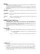
Section 6-1 Response Times The equation for minimum I/O response time is thus as follows: Response time = input ON delay + scan time of PC of Unit 0 + minimum transmission time + scan time of PC of Unit 7 + output ON delay Inserting the following values into this equation produces a minimum I/O response time of 99 ms. Maximum Response Time Input ON delay 1.5 ms Output ON delay 15 ms Scan time of PC of Unit 0 20 ms Scan time of PC of Unit 7 50 ms Minimum transmission time 12.
Section 6-1 Response Times The equation for maximum I/O response time is as follows: Response time = input ON delay + (scan time of PC of Unit 0 x 3) + (PC Link polling time x 2 + induction sequence processing time) + (scan time of PC of Unit 7 x 2) + output ON delay Inserting the same values plus the following values into this equation produces a maximum I/O response time of 236.5 ms.
Section 6-1 Response Times PC Link polling time: 30 ms Induction sequence processing time: 120 ms In a Multilevel PC Link System, the time required for the output may be delayed one more scan at both Unit 0 and Unit 7. This is because PC Link servicing is split into two parts in the PC scan, only one of which may be serviced during any one scan depending on the time required for program execution. Refer to the C1000H/C2000H Operation Manual for details.
Section 6-1 Response Times Maximum Response Time The following diagram illustrates the data flow that will produce the maximum response time. Delays occur because signals or data is received just after they would be processed or because data is sent during processing. In either case, processing must wait until the next scan/polling cycle. First output to the buffer in the polling unit is delayed by the setting of the number of LR bits to be refreshed each scan.
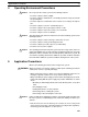
Reducing Response Time (C200H, C200HS, C200HX/HG/HE/(-Z)) 6-2 Section 6-2 Reducing Response Time (C200H, C200HS, C200HX/HG/HE(-Z)) IORF(97) can be used in programming to shorten the I/O response time greater than is possible by setting a high number of refresh bits. (Remember, increasing the number of refresh bits set on the back-panel LED shortens response time, but increases the scan time of the PC.
Section 6-3 Programming Examples 6-3 Programming Examples This example explains the programming required to start the entire Control System shown below only after all “preparation-completed flags” are turned ON for both Subsystems. Using the following programming, any PC that is not in RUN mode will be ignored and operations will continue for the other PCs. The program is designed to start the System only if none of the PCs is already running.
Section 6-3 Programming Examples LR Area Allocations C1000H PC Level 0 C500 PCs Unit 0 LR 00 & LR 01 Unit 0 LR 00 & LR 01 Unit 1 LR 02 & LR 03 Unit 1 LR 02 & LR 03 Unit 2 LR 04 & LR 05 Unit 2 LR 04 & LR 05 Level 0 Unit 3 LR 06 & LR 07 Unit 3 LR 06 & LR 07 Unit 4 LR 08 & LR 09 Unit 4 LR 08 & LR 09 Unit 5 LR 10 & LR 11 Unit 5 LR 10 & LR 11 Unit 6 LR 12 & LR 13 Unit 6 LR 12 & LR 13 Unit 7 LR 14 & LR 15 Unit 7 LR 14 & LR 15 Work bits LR 16 & LR 31 Work bits LR 16 & LR 31 Unit 0 LR 32 & LR 3
Section 6-3 Programming Examples Unit 1, Level 0 Preparations completed flag LR 0201 LR 0000 Unit 1 operations started Unit 1, Level 1 Preparations completed flag LR 1801 LR 1600 Unit 1 operations started Unit 7, Level 0 Preparations completed flag LR 1401 LR 0000 Unit 7 operations started Unit 7, Level 1 Preparations completed flag LR 3001 LR 1600 54 Unit 7 operations started
Section 6-3 Programming Examples This example is for a System with three Subsystems consisting of a C1000H PC, a C2000H PC, thirteen C500 PCs, and a C200H PC as shown below. Programming on the following pages shows the necessary steps for transferring data through the transfer PCs. Not all PCs in the System are described.
Programming Examples Section 6-3 Programming Example 1 Using the above System, the following programming, which is started by turning ON input 0000 in PC (D), will move the contents of DM 0100 from PC (C) to DM 0000 in PC (D). In the table below, the process starts at the right when PC (D) sends a START signal is sent to PC (B).
Programming Examples Section 6-3 Programming Example 2 Using the above System, the following programming, which is started by start input 0000 in PC (A), will compare the contents of DM 0200 in PCs (C) and (D) and output an alarm signal if the contents differ.
SECTION 7 Error Processing The PC Link Units provide various means of monitoring systems operation and resolving errors when they occur. These include LED indications, PC RUN and Error Flags, and, for C200H, C200HS, and C200HX/HG/HE(-Z) systems, Special I/O Unit Error Flags and Restart Bits. 7-1 7-2 7-3 SR Area Flags . . . . . . . . . . . . . . . . . . . . . . . . . . . . . . . . . . . . . . . . . . . . . . . . . . . . . . . . . . . . Error Examples . . . . . . . . . . . . . . . . . . . . . . . . . . . .
Section 7-1 SR Area Flags 7-1 SR Area Flags PC RUN Flags can be read to determine the operational status of each PC to which a PC Link Unit is mounted. All PCs are operational when their PC RUN Flag is ON. PC RUN and Error Flags If there is a transfer error or a power failure for any PC Link Unit, the Error Flag for that Unit will turn ON, and an error message will be sent. When the error is removed (the power comes on or transfer preparation is completed) the Error Flag will go OFF.
Section 7-1 SR Area Flags Special I/O Unit Restart Bits Because the C200H-LK401 is treated as a Special I/O Unit, Special I/O Unit and Error Flags Restart Bits and Error Flags are effective for it. An Error Flag turns ON when (C200H, C200HS, the same Special I/O Unit unit number is assigned to more than one Unit or C200HX/HG/HE(-Z)) when an error has occurred in the refresh cycle between the PC and the Special I/O Unit with the designated unit number.
Section 7-2 Error Examples 7-2 Error Examples Error conditions are indicated by the LEDs as described below. Note Some errors in switch settings (e.g., setting the same unit number for more than on PC Link Unit) will not result in an error display, but will cause LR area data to be in error. LK009 LK401 MEANING Indicates all PC Link Units in this operating level are exchanging data normally. Indicates data exchange is not occurring with any other PC Link Unit.
Section 7-2 Error Examples System Configuration This example will describe error indications on all PC Link Units using the following System configuration. Transmission line breaks will be described at two different points, A and B. Unit 3 has been set for double allocation, and thus is allocated the LR bits and flags from both Unit 3 and Unit 4.
Error Examples Section 7-2 Break at Point B Because Unit 0 receives no response from Unit 1 only, it indicates an error for it, and normal conditions for Units 2 and 3. Since Unit 1 receives no polling signal from Unit 0, it indicates an error for Unit 0. Units 2, 3, and 5 receive signals from each other and indicate normal conditions other than an error for Unit 1. LED indications are shown below, as well as the conditions of the PC RUN and Error Flags in the SR area.
Section 7-3 Error Tables Units 3 and 5 (C200H PC) Allocated to Unit 3. Bit 15 Word 250 0 0 Bit 0 0 0 0 0 1 0 0 0 1 1 Error Flags OFF for Units 2 and 5. 1 1 1 1 PCs operative for all Units. Error Flag OFF for Unit 0. Error Flag ON for Unit 1. Note The C200H could be replaced by the C200HS and C200HX/HG/HE(-Z) without any changes in this example.
Section 7-3 Error Tables C200H, C200HS, and C200HX/HG/HE(-Z) PCs Error Unit #0 PC CPU error Unit #0 Special I/O Unit error Unit #1 Unit #0 Unit #n cable cable cable problem problem problem (missing (missing (missing or broken) or broken) or broken) Error in data reception from Unit #n Unit #n PC CPU error Unit #n Special I/O Unit error Condition At startup Unit #0 Link not established --- During op- All LEDs SR bit eration not lit (link 25415 ON; broken). RUN LED not lit (link broken).
Section 7-3 Error Tables Error List for Special I/O Units (C200H, C200HS, C200HX/HG/HE(-Z)) Because the C200H-LK401 is treated as a Special I/O Unit, the following errors, Error Flags, and Restart Bits are used with it. Error Causes and status Waiting for Special I/O Special I/O Unit has a hardware malUnit start-up. function. PC will not begin operation. Correction Replace the abnormal Special I/O Unit with a new Unit. (Abnormal Unit displays only $s when I/O table is read.) Too many Special I/O Units.
SECTION 8 Inspection and Maintenance 69
Section 8 Inspection and Maintenance PC Link Units should be inspected regularly at the same time as the PCs to which they are attached. The following three areas should be given special attention.
Appendix A Standard Models This chart shows the standard models of the products that are available for use with PC Link Units. Product PC Link Unit Link Adapter Specifications For use with C500, C500F, C1000H, C2000, and C2000H PCs. Multilevel System possible. Includes one RS485 connector and connector cover. For use with C200H, C200HS, and C200HX/HG/HE(-Z) PCs. Multilevel System possible. Includes one RS485 connector and connector cover.
Appendix A Standard Models Plastic-clad Optical Fiber Cable Model numbers with the suffix -P can be connected to up to 200 m of PCF cable. Product Optical fiber cable (indoor) Optical fiber cable (indoor/ outdoor) Note: 72 Description Model number .
Appendix B Specifications Item Communication method Sync Transmission speed Transmission method Transmission distance Possible no. of PC Link Units per System Transmission LR bits Transmission time Diagnostic functions Interface Cable used --Current consumption Weight Specification 2-conductor, half duplex or 4-conductor, half duplex (if optical links are included.
Glossary Backplane A base to which Units are mounted to form a Rack. Backplanes provide a series of connectors for these Units along with wiring to connect them to the CPU. Backplanes also provide connectors used to connect them to other Backplanes. In some Systems, different Backplanes are used for different Racks; in other Systems, Racks differ only by the Units mounted to them.
Glossary data area An area in the PC’s memory that is designed to hold a specific type of data, e.g., the LR area is designed for to hold common data in a PC Link System. distributed control A automation concept in which control of each portion of an automated system is located near the devices actually being control, i.e., control is decentralized and ‘distributed’ over the system. Distributed control is a concept basic to PC Systems.
Glossary linkable slot A slot on either a CPU or Expansion I/O Backplane to which a Link Unit can be mounted. Backplanes differ in the slots to which Link Units can be mounted. Link System A system that includes one or more of the following systems: Remote I/O System, PC Link System, Host Link System, or Net Link System. Link Unit Any of the Units used to connect a PC to a Link System. These are Remote I/O Units, I/O Link Units, PC Link Units, Host Link Units, and Net Link Units.
Glossary polling A method in which one element in a system monitors changes in the contents of certain data words to maintain accurate records of the contents. In a PC Link System, polling is performed by the polling unit to maintain common data areas among PCs. polling unit The PC Link Unit in a PC Link System that handles data transmissions to maintain common data areas within the PCs. In a PC Link System, the polling unit always shares common data areas with the polled units.
Glossary transfer PC A PC that belongs to two PC Link Subsystems (i.e., has two PC Link Units mounted to it). A transfer PC can be used to transfer data between the two PC Link Subsystems to which it belongs. transmission distance The distance that a signal can be transmitted. Unit In OMRON PC terminology, the word Unit is capitalized to indicate any product sold for a PC System. Though most of the names of these products end with the word Unit, not all do, e.g.
Index Numbers 3G2A5–LK009–E, 2 errors example LED indications, 61, 62 general, 66 processing, 55 A-B I application examples, 51 I/O refresh bits (LK401), 26 applications, precautions, xiii indicators, 24, 28 Branching Link Adapter, PC Link System, 10 inspection and maintenance, 67 installation, precautions, xiii C instructions, IORF(97), 51 L C500–LK003–E PC Link Unit, 2 cable connections procedure, 40 cable lengths, 40 connections, 38 wiring connectors, 41 connector hood, assembly, 41 connecto
Index operating level, setting LK009, 32 LK401, 26 operating levels, 3 shield wire connections, 38 shutdown, System, preventing, PC Link System, 6 single–level system example, 8 operation, 17 Special I/O Unit Error Flags, 67 optical fiber cable, PC Link System, 10 Special I/O Unit error list, 66 optical links, 7, 10 Special I/O Unit number, setting (LK401), 25 Special I/O Unit Restart Bits, 67 P Special I/O Unit Restart Bits and Error Flags, 60 specifications, 70 PC Link Subsystem, 6 standard Omr
Revision History A manual revision code appears as a suffix to the catalog number on the front cover of the manual. Cat. No. W135-E1-3 Revision code The following table outlines the changes made to the manual during each revision. Page references are to the previous version of the manual. Revision code 1 2 2A 2B Date --July 1990 July 1994 May 1996 Revised content Original production Complete reorganization and rewrite Correction to switch 5 setting on p. 24 Connector model added to Appendix A.