
Network Card User Manual


55
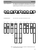
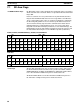
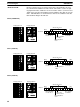
This example is for a System with three Subsystems consisting of a C1000H
PC, a C2000H PC, thirteen C500 PCs, and a C200H PC as shown below.
Programming on the following pages shows the necessary steps for transfer-
ring data through the transfer PCs. Not all PCs in the System are described.
Unit 7 Unit 6 Unit 1 Unit 0 Unit 0 Unit 2
C500 PC
Unit 1 Unit 0 Unit 1 Unit 6 Unit 7
Level 0 Level 1 Level 0
C500 PC C500 PC C500 PC C500 PC C500 PC C200H PC
(A)
C1000H PC
(B)
C2000H PC
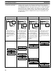
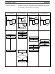
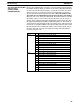
All words below are shown with the Unit that writes to them.
LR 14 &
LR 15
LR 12 &
LR 13
LR 02 &
LR 03
LR 00 &
LR 01
LR 32 to
LR 47
LR 48 to
LR 63
LR 00 &
LR 01
LR 02 &
LR 03
LR 04 &
LR 05
LR 12 &
LR 13
LR 14 &
LR 15
Unit 0,
level 0
Unit 0,
level 0
Unit 0,
level 1
Unit 1,
level 1
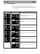
C500 PC
Unit 7
C500 PC
Unit 6
C500 PC
Unit 1
C1000H PC C500 PC
Unit 1
C500 PC
Unit 2
C500 PC
Unit 6
C200H PC
Unit 7
C2000H PC
The C200H could be replaced by the C200HS and C200HX/HG/HE(-Z) with-
out any changes in this example.
System Configuration 2
LR Area Allocations
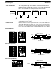
Note
Programming Examples Section 6-3