
Controller Link Units Operation Manual


131
Setting Data Links Section 5-2
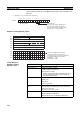
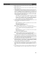
Automatic Setting, 1:N
Allocations
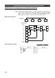
This method is used to simplify the establishment of 1:N allocation data links
between master and slave nodes.
• There are three types of 1:N allocations.
• Programming Devices (including Programming Consoles) are used to set
the automatic data link mode in the DM Parameter Area of the PLC used
as the startup node.
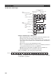
• Node 1 is the master node.
• Area 1 can be set in the bit-access areas and area 2 can be set in the DM
Area.
• The send area sizes of the master and slave nodes are the same for each
area.
• Send nodes are in the same ascending order as node numbers.
• All nodes can be specified to either participate or not participate in the
data link.
• The data link areas (data link start words) are common to all nodes partic-
ipating in the data links.
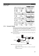
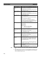
Note 1. Automatic data link creation with 1:N allocations can only be used with the
following Controller Link Units and Support Boards:
2. Controller Link Units and Support Boards other than those listed above
cannot participate in 1:N allocation data links. They can, however, join the
network if a parameter in the DM Parameter Area is set so that they do not
participate in the data links.
3. For automatic data link creation with 1:N allocations, use the CX-Net in CX-
Programmer version 3.2 or higher.
1
4
2
3
1
2
1
3
1
4
1
4
2
3
1
2
1
3
1
4
Node 1 Node 2 Node 3 Node 4
Area 1
Area 2
Type Model
Wired networks CS1W-CLK21-V1 (for CS Series)
CJ1W-CLK21-V1 (for CJ Series)
3G8F7-CLK21-V1 (for PCI bus)