
Controller Link Units Operation Manual

259
Data Link I/O Response Time Section 8-3
mum number of words (1,200 words) per time.
For example, if the total number of data link words is 5,000, the result will be
as shown below.
5,000/1,200 = 2.5 (approx. 3)
Cycle time of PLC at node #7
× (2+3)
The PLC cycle time when data link words exceed 12,000 using a CS/CJ-
series Controller Link Unit with unit version 1.2 or later is calculated as fol-
lows.
12,000 to 15,600 (approx.) words:
× 3
15,600 (approx.) to 20,000 words:
× 4
Noise may increase I/O delays.
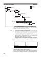
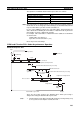
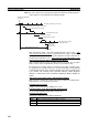
Case 3
The following diagram illustrates the data flow that will produce the maximum
data link I/O response time when the cycle time of the PLC at node #1 < the
communications cycle time and the cycle time of the PLC at node #7
≥ the
communications cycle time.
There are four points shown in the diagram above where processing is
delayed, increasing the data link I/O response time.
1,2,3... 1. The input arrives in the PLC just after I/O refreshing, causing a delay of up
to one cycle before the input is read into the PLC.
2. At point A, data from the previous exchange is still being transferred, so
new data cannot be exchanged, causing a delay of one communications
cycle time. Furthermore, the data exchange then occurs just after the PLC
at node #1 passes the token for the polling node, causing another delay of
one communications cycle time before the data is transferred in data link
processing.
Input device
Program
Program
Input
Input ON delay
1 cycle
Out
p
ut
Output device
Output ON delay
1 cycle
Communications
cycle time
Data link transmission
Controller Link Unit
transmission processing
PLC at node #7
(1)
I/O refresh
Data exchange
Controller Link Unit
transmission processing
PLC at node #1
Previous communications
cycle data
Data link I/O response time
X
X
X
(2)
(3)
(4)
A
X