
Controller Link Units Operation Manual

263
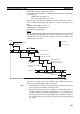
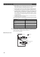
Data Link I/O Response Time Section 8-3
The equation for minimum data link I/O response time is as follows:
Note If the total number of data link words is greater than the maximum number of
words that can be exchanged per data exchange, the maximum data link I/O
response time will be cycle time of PLC at node #7
× 3.
In case of the CQM1H, however, the cycle time will be incremented by the
value obtained from dividing the total number of data link words by the maxi-
mum number of words (1,200 words) per time.
For example, if the total number of data link words is 5,000, the result will be
as shown below.
5,000/1,200 = 2.5 (approx. 3)
Cycle time of PLC at node #7
× (1+3)
Noise may increase I/O delays.
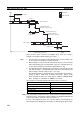
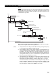
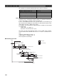
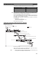
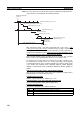
CVM1 and CV-series PLCs Under Asynchronous Operation
Maximum Response Time
There are five points shown in the diagram above where processing is
delayed, increasing the data link I/O response time.
1,2,3... 1. The input arrives in the PLC just after I/O refreshing, causing a delay of up
to one cycle before the input is read into the PLC.
Input ON delay ---
Cycle time of PLC at node #1 15 ms
PLC cycle time at node #7 (See note.) 20 ms (See note.)
Output ON delay ---
Total (data link I/O response time) 35 ms
Controller Link Unit transmission processing
Program
(1)
(2)
(3)
(4)
Input
Input device
Input ON delay
1 cycle
Program
PLC at node #1
PLC at node #7
Data link transmission
Controller Link Unit transmission processing
Communications
cycle time
Output device
Output ON
delay
Output
Data link I/O response time
Peripheral servicing interval
I/O refresh
Previous communica-
tions cycle data
1 cycle
Peripheral servicing interval