
Controller Link Units Operation Manual


272
Message Delay Times Section 8-4
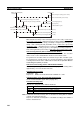
interval (destination node) + Transmission processing (response) + Communi-
cations cycle + Transmission delay (response) + Reception processing
(response) + Link Unit servicing interval (source node).
Link Servicing Interval (Source and Destination Nodes)
Link service processing is the same as the PLC’s peripheral servicing and is
approximately 1 ms for Controller Link Units.
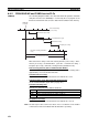
Transmission Processing
Commands: 2 ms
Responses: Number of words transferred
× 0.00125 ms + 3 ms
Communications Cycle Time (with Data Links Inactive)
See 8-2 Communications Cycle Time (on page 251).
Transmission Delay Time
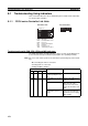
Transmission delay time varies with the baud rate.
Note Commands: Transmission delay time is calculated assuming that the number
of words to be transferred is zero.
Responses: Transmission delay time is calculated according to the number of
words to be transferred.
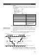
Reception Processing
Commands: 2.3 ms
Responses: Number of words transferred
× 0.00125 ms + 2.3 ms
The I/O response time might increase due to noise or restrictions on the num-
ber of frames that can be transmitted while the data link is operating.
Example
In this example, the maximum transmission delay is calculated for an instruc-
tion receiving 256 words of data in a system with 32 nodes. Network specifics
are detailed below:
Baud rate: 2 Mbps
Max. node number: 32
Number of nodes: 32
Number of polled nodes: 4
Number of words: 256
Data links: Halted
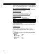
Baud rate Transmission delay time
2 Mbps Number of words transferred × 0.008 + 0.112 ms
1 Mbps Number of words transferred × 0.016 + 0.224 ms
500 Kbps Number of words transferred × 0.032 + 0.448 ms