
Controller Link Units Operation Manual

326
Handling Precautions Section 9-6
CVM1 and CV-series Controller Link Units
CQM1H-series Controller Link Units
2. Turn the power off once, connect the Controller Link Network and turn the
power on again. Check that the Unit is participating in the Network.
If the INS indicator is lit and the ERC and ERH indicators are off, then the
Unit is in the Network.
3. Return the Polled node/polling node setting of the node in which the Unit
was replaced to “polling node.” For C200HX/HG/HE and CQM1H-series
Controller Link Units, the EEPROM Clear bit will already be set to not clear
EEPROM.
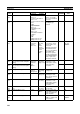
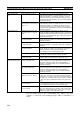
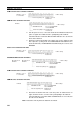
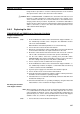
CS/CJ-series Controller Link Units
C200HX/HG/HE Controller Link Units
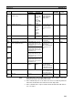
CVM1 and CV-series Controller Link Units
CQM1H-series Controller Link Units
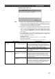
4. Restart the Controller Link Unit or turn the power off and then back on
again, and then check to see if the Unit is participating in the Network.
If the INS indicator is lit and the ERC and ERH indicators are not lit, then
the Unit is in the Network.
Note Restart the Unit only when the data links are halted.
0: Polling node mode
1: Polled node
Polled node/polling node
– : Other settings
DM 2000 + 100 × n
n = Unit number
DM 6400
–: Other settings
EEPROM Clear Bit 0: Do not clear EEPROM
1: Clear EEPROM
Polled node/polling node 0: Polling node
1: Polled node
0: Polling node
1: Polled node
Polled node/Polling node
– : Other settings
DM 30000 + 100 × n
n = Unit number
−
Operating level 0
DM 6400
Operating level 1
DM 6420
–: Other settings
EEPROM Clear Bit 0: Do not clear EEPROM
1: Clear EEPROM
Polled node/polling node 0: Polling node
1: Polled node
0: Polling node mode
1: Polled node
Polled node/Polling node
– : Other settings
DM 2000 + 100 × n
n = Unit number
DM 6400
–: Other settings
EEPROM Clear Bit 0: Do not clear EEPROM
1: Clear EEPROM
Polled node/polling node 0: Polling node
1: Polled node