
Controller Link Units Operation Manual


354
Memory Areas Appendix B
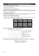
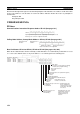
Words N+22 through N+25 register nodes that will participate in the data links. The numbers shown in the table
are the node addresses. The bit status for each node address indicates whether the node is to participate in
the data links.
Participate: ON
Not participate: OFF
C200HX/HG/HE PLCs
SR Area
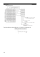
Communications Instruction Response Codes: SR 237 (See page 191.)
Polling Node Address, Startup Node Address: SR 238, SR 242 (See page 300.)
Data Link Status: SR 239 to SR 241, SR 243 to SR 245 (See pages 156, 300.)
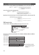
When the first data link status word for manually set data link tables or for automatically set data links is not set
or is set to 0, the data link status of only node addresses 1 to 6 will be given in the following area.
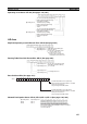
Operating level 0 response codeOperating level 1 response code
Each response code is in 2-digit hexadecimal.
SR 237
Operating level 0
SR 238
Operating level 1
SR 242
Polling node address Startup node address
Each node address is in 2-digit BCD.
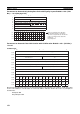
Operating
level 0
SR 239
SR 240
SR 241
Operating
level 1
SR 243
SR 244
SR 245
PLC status
0: Inactive (user program not running)
1: Active (user program running)
Communications error (data link reception)
0: Normal
1: Error
PLC's CPU Unit error
0: Normal
1: Error
Data link participation
0: Not in data link or data link inactive
1: In data link
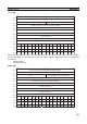
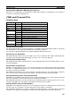
Offset error
0: Normal
1: Error
Error: Offset exceeds
number of send words.
Insufficient (short) receive area
0: Sufficient
1: Insufficient
Insufficient: Receive
area is smaller than
send area. Excess data
is truncated; other data
is received.
Remaining receive area
0: Not remaining
1: Remaining
Remaining: Receive area
is larger than send area.
Data is received and
remaining words are
cleared.
Node 2
Node 4
Node 6
Node 1
Node 3
Node 5