
Controller Link Units Operation Manual


32
Data Links Procedures Section 2-1
2-1 Data Links Procedures
2-1-1 Manually Setting Data Links
When the data link mode is set for manual data link table creation, the data
link tables can be input using the Controller Link Support Software or CX-Pro-
grammer. Use the following procedure.
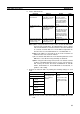
1,2,3... 1. Install and wire the Units.
2. Prepare for communications.
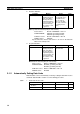
3. Turn ON the power to the PLC.
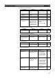
4. Connect the Programming Device.
5. Create I/O tables.
Contents Method Nodes Page
a. Mount the Units to
the PLCs.
--- All nodes 59
b. Wire the Network.
--- All nodes 66
Contents Method Nodes Page
a. Set the unit num-
ber.
Use the front rotary
switches.
CS/CJ-series, CVM1,
and CV-series PLCs
only
98
b. Set the node
address.
Use the front rotary
switches.
All nodes 94,98
c. Set the baud rate.
Use the DIP switch. All nodes 95, 99
d. Set the operating
level.
Use the DIP switch. C200HX/HG/HE PLCs
only
95
e. Set the terminal
resistance
Use the front switch
for CVM1, CV-series,
CS/CJ-series, and
CQM1H-series PLCs
or the bottom switch
for C200HX/HG/HE
PLCs.
All nodes
End nodes on the net-
work: ON
All other nodes: OFF
96, 99
Contents Method Nodes Page
Turn ON the power to
the PLC.
--- All nodes ---
Contents Method Nodes Page
Connect the Program-
ming Console or Con-
troller Link Support
Software.
Use the special con-
nection cable.
CS/CJ-series, CVM1,
and CV-series PLCs
21
Contents Method Nodes Page
Input the I/O tables. Use the Support Soft-
ware or Programming
Console.
CS/CJ-series, CVM1,
and CV-series PLCs
only
---