
Controller Link Units Operation Manual


68
Wiring Section 3-3
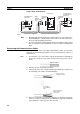
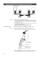
Using a Relay Terminal Block
Note 1. Mounting and dismounting during communications is not possible for Re-
lay Terminal Blocks connected to the nodes at the ends of the network (i.e.:
the nodes with terminating resistance).
2. Use the recommended crimp terminals when connecting the cable’s signal
lines or shield line to the terminal blocks. Short circuits can damage the
Units.
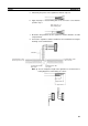
Connecting the Communications Cables
Use crimp terminals when connecting communications cables to a Controller
Link Unit. Use the following procedure to connect communications cables to a
terminal block.
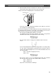
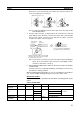
1,2,3... 1. Peel back the cover of the cable for about 50 mm without scratching the
mesh of the shield. Do not peel too much because it may cause a short-
circuit.
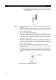
2. Twist the mesh of the shield to form a line.
3. Leave the tip of the wire created by twisting the shield exposed and cover
the remaining section with a heat-shrinking tube.
4. Remove enough of the cover from the signal lines to allow the crimp termi-
nals to be connected, taking care not to damage the signal lines. Damage
to the signal lines could cause the cable to break.
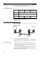
TER SW
↓
ON
BD H
BD L
SHLD
TER
SW
↓
ON
↓
ON
BD H
BD L
SHLD
TER SW
BD H
BD L
SHLD
C200HW-CLK21
(End node)
Terminating
resistance
(ON)
Ground
Terminating
resistance
(OFF)
CVM1-CLK21
Terminating
resistance
(ON)
CS1W-CLK21-V1
CJ1W-CLK21-V1
(End node)
Relay
Terminal
Block (see
note 1.)
Approx. 50 mm
Wire created by
twisting the shield
Cover with a
heat-shrinking
tube
Exposed portion for
crimp terminal
connection