
Controller Link Units Operation Manual


76
Wiring Section 3-3
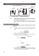
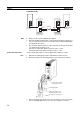
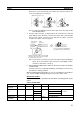
CS1W-RPT03 (GI)
Note 1. Always use the specified Optical Fiber Cables.
2. Although the Optical Fiber Cables can be distinguished by the markings or
color, in order to prevent incorrect connection it is recommended that tags
are attached to the cables.
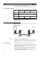
3. The maximum distance between nodes depends on the type of GI cable
(core diameter) that is being used.
62.5/125
µm cable: Max. distance between nodes = 2 km
50/125
µm cable: Max. distance between nodes = 1 km
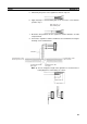
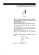
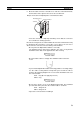
Connection Procedure Use the following procedure to connect Optical Fiber Cables to a Unit.
1,2,3... 1. Attach the mounting bracket to the Unit with the provided screws.
2. Attach the clamp to the mounting bracket so that it clamps the cable(s).
3. Remove the Optical Connector Covers from the Unit’s connectors shown
in the following diagram if there are covers protecting the connectors.
GI cable
SL1
SL2
SL1
SL2
Send
Wired Controller
Link Unit
Wired Controller
Link Unit
CS1W-RPT03
Repeater Unit
CS1W-RPT03
Repeater Unit
Receive
Send
Receive
Mounting bracket
Clamp
1. Screw the mounting
bracket to the Unit.
2. Attach the clamp to the
mounting bracket so that
the cable(s) are clamped.