
Controller Link Units Operation Manual

145
Setting Data Links Section 5-2
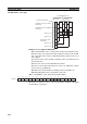
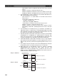
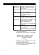
11. If the LR Area in the C200HX/HG/HE or CQM1H-series PLC is automati-
cally set for a data link with a CVM1, CV-series PLC or CS/CJ-series PLC,
the LR words will be linked to CIO 1000 to CIO 1063 in the CVM1, CV-se-
ries or CS/CJ-series PLC. CIO 1064 to CIO 1199 cannot be linked with
C200HX/HG/HE or CQM1H-series PLCs in this way.
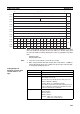
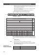
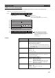
C200HX/HG/HE Startup Node
Set the following DM Parameter Area of the PLC of the startup node.
Settings
Cannot be directly linked
with C200HX/HG/HE words.
LR00
LR63
to
1000
1063
to
1064
1199
to
CS/CJ-series PLCs
IR words of CS/CJ-series PLCs
= (LR words of C200HX/HG/HE or
CQM1H-series PLC) + 1000
C200HX/HG/HE or
CQM1H-series PLCs
Data link mode
Set to 01 for automatic setting.
(00 is for manual setting. Other values are invalid.)
Area 1 data link start word (BCD)
Area 1 type
Number of send words per node of area 1 (BCD)
Rightmost 4 digits of data link start word of area 2 (DM area) (BCD)
Leftmost digit of data link start word of
area 2 (BCD)
First data link status word (BCD)
BCD: Set the value as binary-coded decimal.
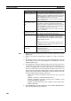
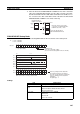
Nodes to participate in the data links
The numbers indicate node numbers.
The value assigned indicates whether the
node is to participate in the data links.
Participate: 1
Not participate: 0
Word N
0: Always specify 0.
– : By other setting
15 14 13 12 11 10 9 8 765 4 3 2 10
15 8 7
0
15 14 13 12 11 10 9 8 7 6 5 4 3 2 10
1615141312111098765432
1
N+1
N+2
N+3
N+4
N+5
N+6
N+7
N+8
32 31 30 29 28 27 26 25 24 23 22 21 20 19 18 17
N+9
––
0
–
000000 0000
N: Level 0 = DM 6400
Level 1 = DM 6420
Area 2 type
Number of send words per node of area 2 (BCD)
00
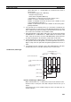
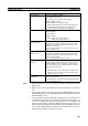
Item Setting range
Data link mode Specify automatic (01).
Area 1 data link start
word
Set the word address in BCD.
IR Area: IR 000 to IR 235, IR 300 to IR 511
LR Area: LR 00 to 63
Area 1 type Set the area for area 1 in BCD.
IR Area: 80
LR Area: 86
Area 1 not used: 00