
Controller Link Units Operation Manual

294
Status Area and Troubleshooting Section 9-2
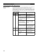
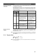
Note Data link status is valid only when the local node is participating in the data
link. Confirm that the Local Data Link Active Bit is ON before referencing the
data link status.
The statuses of bits 12 to 14 are reflected only when using a CS1W-CLK21-
V1 or CJ1W-CLK21-V1.
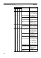
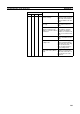
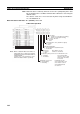
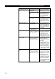
Data Link Status: CIO 1500 + 25
× (Unit No.) + 7 to + 22
8-Bit Format Specified
Node 2
Node 4
Node 6
Node 8
Node 12
Node 14
Node 16
Node 18
Node 22
Node 24
Node 26
Node 28
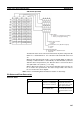
PLC status
0: Inactive (user program not running)
1: Active (user program running)
Communications error (data link reception)
0: Normal
1: Error
PLC's CPU Unit error
0: Normal
1: Error
Data link participation
0: Not in data link or data link inactive
1: In data link
Offset error
0: Normal
1: Error
Error: Offset exceeds
number of send words.
Insufficient (short) receive area
0: Sufficient
1: Insufficient
Insufficient: Receive
area is smaller than
send area. Excess data
is truncated; other data
is received.
Remaining receive area
0: Not remaining
1: Remaining
Remaining: Receive
area is larger than send
area. Data is received
and remaining words
are cleared.
Node 1
Node 3
Node 5
Node 7
Node 11
Node 13
Node 15
Node 17
Node 21
Node 23
Node 25
Node 27
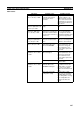
+7
+8
+21
+22
Note When a data link with node addresses
higher than 32 is required, specify the
beginning storage word rather than us-
ing the default.
(In this case, a 31 word area is used
when the 8-bit format is specified.)
+20
+19
+18
Node 10
Node 20
Node 9
Node 19
Node 30 Node 29
Node 32 Node 31
+16
+17
+15
+14
+13
+12
+11
+10
+9