
Controller Link Units Operation Manual

349
Memory Areas Appendix B
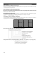
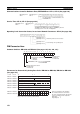
Network Participation Status: CIO 1500 + 25 × (Unit No.) + 2, + 3 (See pages 190, 304.)
Local Data Link Participation Status: CIO 1500 + 25
× (Unit No.) + 6 (See page 304.)
Data Link Status: CIO 1500 + 25
× (Unit No.) + 7 to + 22 (See pages 156, 305.)
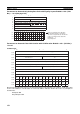
When the first data link status word for manually set data link tables or for automatically set data links is not set
or is set to 0, the data link status is stored in the words shown below.
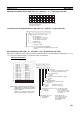
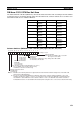
8-Bit Format Specified
The numbers in the squares indicate node addresses.
The corresponding node participation status is as follows:
0: Not part of the network
1: Part of the network
+ 2
+ 3
15 14 13 12 11 10 9 8 7 6 5 4 3 2 1 0
16 15 14 13 12 11 10 9 8 7 6 5 4 3 2 1
32 31 30 29 28 27 26 25 24 23 22 21 20 19 18 17
+ 4
48 47 46 45 44 43 42 41 40 39 38 37 36 35 34 33
+ 5
−−62 61 60 59 58 57 56 55 54 53 52 51 50 49
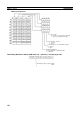
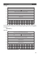
1: Local node data link participating
0: Local node data link not participating or data link
inactive
Allocation for automatic setting
00: Equality layout
01: 1:N allocation, common type
10: 1:N allocation, 1 to 1 type
11: 1:N allocation, chain type
Data link mode
0: Manual setting
1: Automatic setting
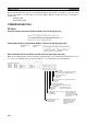
Node 2
Node 4
Node 6
Node 8
Node 12
Node 14
Node 16
Node 18
Node 22
Node 24
Node 26
Node 28
PLC status
0: Inactive (user program not running)
1: Active (user program running)
Communications error (data link reception)
0: Normal
1: Error
PLC's CPU Unit error
0: Normal
1: Error
Data link participation
0: Not in data link or data link inactive
1: In data link
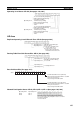
Offset error
0: Normal
1: Error
Error: Offset exceeds
number of send words.
Insufficient (short) receive area
0: Sufficient
1: Insufficient
Insufficient: Receive
area is smaller than
send area. Excess data
is truncated; other data
is received.
Remaining receive area
0: Not remaining
1: Remaining
Remaining: Receive
area is larger than send
area. Data is received
and remaining words
are cleared.
Node 1
Node 3
Node 5
Node 7
Node 11
Node 13
Node 15
Node 17
Node 21
Node 23
Node 25
Node 27
+7
+8
+21
+22
Note When a data link with node addresses
higher than 32 is required, specify the
beginning storage word rather than us-
ing the default.
(In this case, a 31 word area is used
when the 8-bit format is specified.)
+20
+19
+18
Node 10
Node 20
Node 9
Node 19
Node 30 Node 29
Node 32 Node 31
+16
+17
+15
+14
+13
+12
+11
+10
+9