
Controller Link Units Operation Manual

44
Component Names and Functions Section 3-1
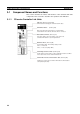
3-1 Component Names and Functions
This section describes the names and functions of the Controller Link Unit
components. This section also describes the operation of the indicators.
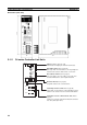
3-1-1 CS-series Controller Link Units
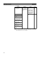
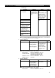
Unit number switch
One rotary switch. The unit number is set in single-digit
hexadecimal for the network to which the PLC is connected.
Indicators
LED indicators that display the Unit and network status.
Node address switches
Two rotary switches. The node address of the Unit on the
Controller Link Network is set in 2-digit decimal.
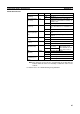
Baud rate switch
A four-pin DIP switch. The following setting is made.
Pins 1, 2: Baud rate
Pins 3, 4: Not used (always OFF)
Terminal block for the communications cable
Terminals to connect to the Controller Link Network communications
cable
(
twisted-
p
air cable
)
.
Terminating resistance switch
A slide switch. Use this switch to set the terminating resistance to ON for
nodes at both ends of the Controller Link Network.
CLK21-V1
(Refer to p.45 and 276)
(Refer to p.86)
(Refer to p.87)
(Refer to p.88)
(Refer to p.89)
(Refer to p.66)