
Datasheet
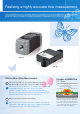
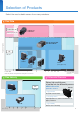
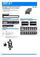
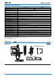
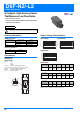
Table Of Contents
- D6F-A1
- A Compact, High-Acuracy Sensor That Measures Low Flow Rates.
- Characteristics/Performance
- Characteristics/Performance
- Characteristics/Performance
- Characteristics/Performance
- Characteristics/Performance
- Characteristics/Performance
- Dimensions (Unit: mm)
- Note. The Port type of pipe fitting based on “Quick Joint P10 Type”.
- * P10 shows the name of an O-ring prescribed by JIS B 2401.
- * The port of O-ring ditch is based on P10 of JIS B 2406.
- * Please obtain a male joint separately.
- D6F-A7D/-AB71D
- Digital Compensation for High Accuracy
- . Temperature compensation and linear compensation produce high accuracy (±3% RD (25% to 100% FS)).
- . Compact models for 10 to 70 L/min.
- . Reduced piping work with quick-fastening feature.
- Ordering Information
- Connections
- Output Characteristics
- Measurement conditions: Power-supply voltage 3.3±0.1 VDC, ambient temperature 25±5˚C and ambient humidity 35 to 75%RH.
- Flow rate = (Output value - 1,024)/60,000 x 10
- Measurement conditions: Power-supply voltage 3.3±0.1 VDC, ambient temperature 25±5˚C and ambient humidity 35 to 75%RH.
- Flow rate = (Output value - 1,024)/60,000 x 20
- Measurement conditions: Power-supply voltage 3.3±0.1 VDC, ambient temperature 25±5˚C and ambient humidity 35 to 75%RH.
- Flow rate = (Output value - 1,024)/60,000 x 50
- Measurement conditions: Power-supply voltage 3.3±0.1 VDC, ambient temperature 25±5˚C and ambient humidity 35 to 75%RH.
- Flow rate = (Output value - 1,024)/60,000 x 100
- Characteristics/Performance
- Note: 1. Volumetric flow rate at 0°C, 101.3 kPa.
- Note: 2. Dry gas (must not contain large particles, e.g., dust, oil, or mist.)
- Note: 3. -10 £ Operating Temperature £ 60°C
- Note: 4. Reference (typical)
- Note: 5. Refer to the MEMS Flow Sensor D6F-A7D/-AB71D User's Manual for details.
- Note: 6. With no condensation or icing.
- Note: 7. The following custom options are available. Ask your OMRON representative for details. - Temperature measurement - Address settings (up to four addresses) - Fault detection - Threshold setting
- Communication
- The D6F-A7D/-AB71D MEMS flow sensor can be connected to the OMRON sensor evaluation board.
- The following three platforms are supported, and evaluation can easily be performed by connecting the flow sensor, evaluation board, and harness to the platform.
- For more information about the evaluation board, please visit the following URL.
- (https://components.omron.com/sensor/evaluation-board/2jcie)
- Dimensions (Unit: mm)
- Characteristics/Performance
- Dimensions (Unit: mm)
- D6F-P
- A Compact, High-Acuracy Flow Sensor with Superior Resistance to Environments.
- Characteristics/Performance
- Tubing
- Connections/Dimensions (Unit: mm)
- D6F-PH
- A Compact, High-Acuracy Differential Pressure Sensor with Superior Resistance to Environments.
- . High accuracy of ±3% RD
- . Linearized and temperature compensated
- . Digital output (I2C communication)
- . High flow impedance to reduce the influence of bypass configuration
- Ordering Information
- Note. Models with different slave addresses are also available. Consult your OMRON representative for details.
- Note: 1. The Sensor be calibrated for different gas types. Consult your Omron representative.
- Note: 2. Dry gas must not contain large particles, e.g., dust, oil, or mist.
- Note: 3. At standard atmospheric pressure (1013.25 hPa)
- Note. This cable is for connection with the D6F-PH0025AD2, D6F-PH0025AMD2, D6F-PH0505AD4, D6F-PH0505AMD4, D6F-PH5050AD4, and D6F-PH5050AMD4 connector-type models. One side is a connector and the other side is a lead wire.
- Note. Refer to Accessories for the D6F Series on page 38.
- The D6F-PH MEMS differential pressure sensor can be connected to the OMRON sensor evaluation board.
- The following three platforms are supported, and evaluation can easily be performed by connecting the differential pressure sensor, evaluation board, and harness to the platform.
- For more information about the evaluation board, please visit the following URL.
- (https://components.omron.com/sensor/evaluation-board/2jcie)
- For information on how to use the sample code, please refer to the D6F-PH User’s Manual.
- Note: 1. Raspberry Pi is a registered trademark of the Raspberry Pi Foundation.
- Note: 2. Arduino is a registered trademark of Arduino LLC and Arduino SRL.
- Note: 3. Feather is a registered trademark of Adafruit Industries LLC.
- Note: 4. The 2JCIE-HARNESS-02 is a connector on one side and a lead wire on the other. The lead wire must be connected to the D6F-PH for use.
- Note: 5. The 2JCIE-HARNESS-03 has connectors on both sides. Both the D6F-PH and the evaluation board can be easily connected using these connectors.
- Output Characteristics
- Measurement conditions: Power supply voltage of 3.3 ±0.1 VDC, ambient temperature of 25±5°C, and ambient humidity of 35% to 75%. Differential pressure conversion formula: Dp = (Op - 1024) / 60000 ° 250 Dp = Differential pressure, Op = Output
- Measurement conditions: Power supply voltage of 3.3 ±0.1 VDC, ambient temperature of 25±5°C, and ambient humidity of 35% to 75%. Differential pressure conversion formula: Dp = (Op - 1024) / 60000 ° 100 - 50 Dp = Differential pressure, Op = Output
- Measurement conditions: Power supply voltage of 3.3 ±0.1 VDC, ambient temperature of 25±5°C, and ambient humidity of 35% to 75%. Differential pressure conversion formula: Dp = (Op - 1024) / 60000 ° 1000 - 500 Dp = Differential pressure, Op = Output
- Note. Change of gas density affects the sensor output. Change of atmospheric pressure is compensated by the following formula. D...
- Characteristics/Performance
- Note: 1. At standard atmospheric pressure (1013.25 hPa)
- Note: 2. Dry gas must not contain large particles, e.g., dust, oil, or mist.
- Note: 3. The zero point tolerance and span tolerance are independent uncertainties and add according to the principles of error propagation.
- Note: 4. With no condensation or icing.
- Note: 5. Type D6F-PH is based on thermal flow principle. Air flow is needed to measure the differential pressure. Typical characteristic of air flow by differential pressure is below.
- Tubing (Example for Bamboo Joint)
- Connections/Dimensions (Unit: mm)
- Note. Use M1.8 panhead screws or tapping screws for installation, and tighten the screws to a maximum torque of 0.36 N·m. Use the following connectors to connect to the Sensor.
- Connector : GHR-04V-S (made by J.S.T. Mfg. Co.)
- Terminals : SSHL-002T-P0.2 (made by J.S.T. Mfg. Co.)
- Wires AWG26 to AWG30
- Electrical connection
- Communication
- A Compact Sensor That Uses OMRON’s Unique Flow Path Structure for High-Performance Flow Velocity* Measurement.
- Connections
- Output Voltage Characteristics
- The flow velocity is the value calculated from the mass flow rate in OMRON’s specified 48-mm-dia. wind tunnel. It does not indicate the flow velocity determined by the Measurement Law of Japan. The wind tunnel conditions are shown in Figure 1, below.
- Measurement conditions: Power supply voltage of 12 VDC, ambient temperature of 25°C, and ambient humidity of 35% to 75%.
- The flow velocity is the value calculated from the mass flow rate in OMRON’s specified 155-mm-dia. wind tunnel. It does not indicate the flow velocity determined by the Measurement Law of Japan. The wind tunnel conditions are shown in Figure 2, below.
- Measurement conditions: Power supply voltage of 12 VDC and ambient temperature of 25°C
- Characteristics/Performance
- Dimensions (Unit: mm)
- A Compact Sensor That Uses OMRON’s Unique Flow Path Structure for High-Performance Flow Velocity* Measurement.
- . Anti-dust performance enhanced by OMRON’s unique three-dimensional flow path structure.
- . Extremely compact, measuring only 24 ¥ 14 ¥ 8 mm.
- * The flow velocity is the value calculated from the mass flow rate in OMRON's specified wind tunnel. It does not indicate the flow velocity determined by the Measurement Law of JAPAN.
- Ordering Information
- Connections
- Or
- Output Voltage Characteristics
- The flow velocity is the value calculated from the mass flow rate in OMRON’s specified 48-mm-dia. wind tunnel. It does not indicate the flow velocity determined by the Measurement Law of Japan. The wind tunnel conditions are shown in Figure 1 below.
- Measurement conditions: Power supply voltage of 3.3 VDC, ambient temperature of 25°C, and dry air.
- Output Voltage Characteristics
- Output Voltage Characteristics
- Characteristics/Performance
- Note: 1. Volumetric flow rate at 25°C, 101.3 kPa.
- Dimensions (Unit: mm)
- Dimensions (Unit: mm)
- Safety Precautions
- Precautions for Correct Use
- (1) Use clean fluids. Install a filter or mist separator on the inflow pipe. Failure to do so may result in malfunction or changes in characteristics due to dust or mist. This does not apply to the D6F-W, D6F-V, D6F-P and D6F-PH.
- (2) Do not use corrosive gases other than the specified applicable fluids (such as chlorine, sulfur, acid,or alkali) . Doing so may cause product failure.
- (3) The specified performance may not be obtained if the D6F is used for fluids other than the specified applicable fluids.
- (4) After removing the Sensor from the package, do not allow foreign particles to enter the piping. Foreign particles in the piping may cause product failure.
- (5) Install the sensor so that the fluid flows in the direction indicated by the arrow on the Sensor. Correct measurements cannot be obtained if the fluid flows in the wrong direction. This does not apply to the D6F-V, D6F-P and D6F-PH.
- (6) It is recommended that the Sensor (except for the D6F-A3) be mounted horizontally. If it is not mounted horizontally, an error of ±1% FS or higher may result.
- (7) Install the Sensor on a flat surface. Incorrect installation may damage the Sensor and make it impossible to obtain correct measurements.
- (8) Make sure that the power to all equipment is turned OFF before you install the Sensor. Installing the Sensor while the power supply is ON may result in electrical shock or abnormal operation.
- (9) Always check operation after installation.
- (10) Do not drop the Sensor or disassemble the cover.
- (1) Make sure that pipes with bamboo joints are airtight. Correct measurements cannot be obtained if there is leakage from joints.
- (2) Use M3 panhead screws to install the Sensor, and tighten them to a maximum torque of 0.59 N.m.
- (1) Use the Rc 1/4 tapped threads for the pipes, and tighten the threads to a maximum torque of 5 N.m. Tightening beyond this va...
- (2) Use M3 panhead screws to install the Sensor, and tighten them to a maximum torque of 0.59 N.m.
- (1) When installing the pipes, use M5 screws for the joints and tighten to a torque of 1.5 N.m maximum. Use sealing tape to make the joints airtight. Incorrect installation may make it impossible to obtain correct measurements.
- (2) It is recommended that the Sensor be mounted either horizontally or vertically. Mounting the Sensor at an angle may make it impossible to obtain correct measurements.
- (3) Use M3 panhead screws to install the Sensor, and tighten them to a maximum torque of 0.59 N.m.
- (1) Use M3 panhead screws to install the Sensor, and tighten them to a maximum torque of 0.59 N.m.
- (2) Install O-rings to seal the fluid inlet and outlet points. The recommended O-ring is JIS B 2401, nominal number P5.
- (1) Use the appropriate threads (R1/4, NPT1/8 or NPT1/2) for the pipes, and tighten the pipes to a maximum torque of 5 N.m. Tigh...
- (2) Use M3 panhead screws to install the Sensor, and tighten them to a maximum torque of 0.59 N.m.
- (1) Use male quick couplings for the piping, and secure them with the applicable quick fasteners.
- (2) Do not apply excessive force to the adapter section when connecting the pipes. If strong force is applied to the connected p...
- (1) Depending on the ambient environment and installation location, dust, dirt, and other foreign matter may come in inside the ...
- (2) Attach all tubes so that the fluid flows only in the direction from the positive side (+) to the negative side (-). Refer to the figure on page 26 for the installation direction.
- (3) For PCB-mounting Sensors, perform terminal soldering only after the Sensor is secured into place on the PCB. Use a soldering iron for 5 s at 350°C with a pressure of 100 gf max. (This applies only to PCB-mounting Sensors.)
- (4) Use M2.6 panhead screws or equivalent tapping screws to mount the Sensor, and tighten the screws to a maximum torque of 0.59 N.m.
- (1) Depending on the ambient environment and installation location, dust, dirt, and other foreign matter may come in inside the ...
- (2) Attach all tubes so that the fluid flows only in the direction from the positive side (+) to the negative side (-). Install the Sensor with the manifold facing downward. Refer to the figure on page 26 for the installation direction.
- (3) Use M3 panhead screws or equivalent tapping screws to mount the Sensor, and tighten the screws to a maximum torque of 0.59 N.m.
- (4) Install O-rings to seal the fluid inlet and outlet points. The recommended O-ring is JIS B 2401, nominal number P4.
- (1) Depending on the ambient environment and installation location, dust, dirt, and other foreign matter may come in inside the ...
- (2) Attach all tubes so that the fluid flows only in the direction from the high pressure side (+) to the low pressure side (-).
- (3) Use M1.8 panhead screws or equivalent tapping screws to mount the Sensor, and tighten the screws to a maximum torque of 0.36 N.m.
- (4) The sensor output is affected with the length of a tube. The error is less than 1% with a tube (ID:4mm) length up to 800mm.
- (5) Connection (D6F-PHAD1/-PHAD3)
- (1) Depending on the ambient environment and installation location, dust, dirt, and other foreign matter may come in inside the ...
- (2) Attach all tubes so that the fluid flows only in the direction from the high pressure side (+) to the low pressure side (-).
- (3) Use M3 screws (round head screws) to install the Sensor, and tighten them to a maximum torque of 1.0 N.m. The outer diameter of screw heads and washers must be 6 mm or less. Check that the Sensor is securely fastened by the screws.
- (4) Seal the sealing part of the inlet port with an O-ring. The recommended O-ring is JIS B 2401, nominal number P4.
- (1) Depending on the ambient environment and installation location, dust, dirt, and other foreign matter may come in inside the ...
- (2) Use M3 panhead screws to install the Sensor, and tighten them to a maximum torque of 0.59 N.m.
- (1) Depending on the ambient environment and installation location, dust, dirt, and other foreign matter may come in inside the ...
- (2) Use M3 panhead screws to install the Sensor, and tighten them to a maximum torque of 0.59 N.m.
- (3) This Sensor does not contain any protective circuits. Never allow the electrical load to exceed the maximum ratings. Doing so may damage the circuits. Install protective circuits if required.
- (4) Mount the Sensor so that the flow inlet side (the side with the logo) is perpendicular to the windward side and ensure that ...
- RoHS Directive
- Precautions for Correct Use

MEMS Flow Sensors
D6 F
Series Catalog
Faster and more accurate than ever before
MEMS flow sensor : the ideal means for mass flow measurement
Omron flow sensor
so precise
even the flap of a butterfly’s
wings will not be missed.