Contents Introduction ..................................... 2 5.1ch Home Theater System HT-S580 AV Receiver (HT-R330) Front Speakers (SKF-330F L/R) Center Speaker (SKC-330C) Surround Speakers (SKM-330S L/R) Subwoofer (SKW-330) Instruction Manual Connection .................................... 17 Turning On & First Time Setup..... 32 Basic Operation Playing your AV components ....... 36 Using the Tuner............................ 38 Enjoying the Listening Modes .....
WARNING: TO REDUCE THE RISK OF FIRE OR ELECTRIC SHOCK, DO NOT EXPOSE THIS APPARATUS TO RAIN OR MOISTURE. CAUTION: TO REDUCE THE RISK OF ELECTRIC SHOCK, DO NOT REMOVE COVER (OR BACK). NO USER-SERVICEABLE PARTS INSIDE. REFER SERVICING TO QUALIFIED SERVICE PERSONNEL.
Precautions 1. Recording Copyright—Unless it’s for personal use only, recording copyrighted material is illegal without the permission of the copyright holder. 2. AC Fuse—The AC fuse inside the unit is not userserviceable. If you cannot turn on the unit, contact your Onkyo dealer. 3. Care—Occasionally you should dust the unit all over with a soft cloth. For stubborn stains, use a soft cloth dampened with a weak solution of mild detergent and water. Dry the unit immediately afterwards with a clean cloth.
Precautions—Continued Speaker Precautions For U.S. models Placement FCC Information for User • The subwoofer cabinet is made out of wood and is therefore sensitive to extreme temperatures and humidity, do not put it in locations subject to direct sunlight or in humid places, such as near an air conditioner, humidifier, bathroom, or kitchen. • Do not put water or other liquids close to the speakers. If liquid is spilled over the speakers, the drive units may be damaged.
Features Amp • 6-channel amplifier • 100 watts per channel min. RMS at 8 Ω, 2 channels driven from 1 kHz with no more than 0.
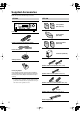
Supplied Accessories Make sure you have the following accessories: HT-R330 HTP-330 Front speakers (SKF-330F L/R) HT-R330 Center speaker (SKC-330C) Remote controller & two batteries (AA/R6) Surround speakers (SKM-330S) Indoor FM antenna Subwoofer (SKW-330) AM loop antenna (Red) (White) Speaker cable for front speakers 15 ft. (4.5 m) Power-plug adapter Only supplied in certain countries. Use this adapter if your AC outlet does not match with the plug on the AV receiver’s power cord.
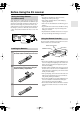
Before Using the AV receiver Setting the Voltage Selector (on some models) Some models have a voltage selector switch for compatibility with power systems around the world. Before you plug in this model, make sure that the voltage selector is set to the correct voltage for your area. If it isn’t, use a small screwdriver to set it as appropriate. For example, if the voltage in your area is 120 volts, set the selector to “120V.” If it’s between 220 and 230 volts, set it to “220230V.
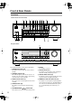
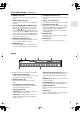
Front & Rear Panels Front Panel North American and Asian Models 2 1 3 4 5 6 78 9J K L M TUNING / PRESET MASTER VOLUME STANDBY/ON ENTER STANDBY A SPEAKERS B + TONE STEREO LISTENING MODE DISPLAY DIGITAL INPUT DIMMER RETURN MEMORY TUNING MODE SETUP CLEAR PHONES N O MULTl CH DVD VIDEO 1/VCR VIDEO 2 P VIDEO 3 TAPE TUNER Q CD R S European Models 9 TUNING / PRESET MASTER VOLUME STANDBY/ON ENTER STANDBY A SPEAKERS B + TONE STEREO LISTENING MODE DISPLAY DIGITAL INPUT
Front & Rear Panels—Continued J MEMORY button (39) O SPEAKER A & B buttons (36) This button is used when storing or deleting radio presets. These buttons are used to turn speaker sets A and B on or off. K TUNING MODE button (38) P TONE, [–] & [+] buttons (42) This button is used to select the Auto or Manual tuning mode. These buttons are used to adjust the bass and treble.
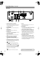
Front & Rear Panels—Continued Rear Panel 1 8 B 9 J 3 4 K 5 6 7 L A DIGITAL IN OPTICAL & COAXIAL These optical and coaxial jacks can be used to connect a CD or DVD player and other components with digital audio outputs. B AM ANTENNA These push terminals are for connecting an AM antenna. C FM ANTENNA This jack is for connecting an FM antenna. D MONITOR OUT The composite video output should be connected to a video input on your TV or projector.
Speaker Package Front, Center, Surround, & Subwoofer speakers (SKF-330F, SKC-330C, SKM-330S, SKW-330) A Speaker terminals ■ Rear These push terminals are for connecting the speaker to the HT-R330 with the supplied speaker cables. The supplied speaker cables are color-coded for easy identification. Simply connect each cable to the same-colored positive speaker terminal. SKF-330F SKM-330S 2 B Keyhole slots These keyhole slots can be used to wall-mount the speaker. See page 19 for mounting instructions.
Remote Controller How to Use the Remote Controller Including the AV receiver, the remote controller can be used to control up to six different components. The remote controller has a specific operating mode for use with each type of component. Modes are selected by using the five REMOTE MODE buttons. RECEIVER mode is used to control the AV receiver. To set the remote controller to RECEIVER mode, press the [RECEIVER] REMOTE MODE button.
Remote Controller—Continued For detailed information, see the pages in parentheses. A STANDBY button (32) This button is used to set the AV receiver to Standby. B ON button (32) This button is used to turn on the AV receiver. C INPUT SELECTOR buttons (36) These buttons are used to select the input sources. D MULTI CH button (37) This button is used to select the multichannel DVD input. E DIMMER button (42) This button is used to adjust the display brightness.
Remote Controller—Continued A STANDBY button DVD Mode This button sets the DVD player to Standby. To set the remote controller to DVD mode, press the [DVD] REMOTE MODE button. Before selecting DVD mode and starting playback, you should press the [RECEIVER] mode button followed by the [DVD] INPUT SELECTOR button to select the DVD player as the input source. B ON button This button is used to turn on the DVD player.
Remote Controller—Continued A STANDBY button CD, MD, & CDR Mode To set the remote controller to CD, MD, or CDR mode, press the [CD], [MD], or [CDR] REMOTE MODE button. Before selecting a mode and starting playback, you should press the [RECEIVER] mode button followed by the [CD] or [TAPE] INPUT SELECTOR button to select the CD player, MiniDisc, or CD recorder as the input source. This button sets the CD player or MD/CD recorder to Standby.
Remote Controller—Continued A Play [ ] button TAPE Mode This button is used to start playback. TAPE mode is used to control an Onkyo cassette recorder connected to the AV receiver via . To set the remote controller to TAPE mode, press the [RECEIVER] REMOTE MODE button. Before selecting TAPE mode and starting playback, you should press the [RECEIVER] REMOTE MODE button followed by the [TAPE] INPUT SELECTOR button to select your cassette recorder as the input source.
Connecting Your Speakers Enjoying Home Theater You can use two sets of speakers with the AV receiver: speaker set A and speaker set B. Speaker set A should be installed in your main listening room and can be used with Dolby Digital and DTS surround material. Each speaker must be positioned at a specific location in your listening room to get the best from surround sound material. The following illustration shows the best positions for your surround-sound speakers.
Connecting Your Speakers—Continued Speaker Connection Precautions Read the following before connecting your speakers: • You can connect speakers with an impedance of 8 ohms or higher. If you use speakers with a lower impedance, and use the amplifier at high volume levels for a long period of time, the built-in protection circuit may be activated. • Disconnect the power cord from the wall outlet before making any connections. • Pay close attention to speaker wiring polarity.
Connecting Your Speakers—Continued Wall Mounting Using Speaker Mounts/Brackets The speakers can easily be wall mounted by using the keyhole slots. To prevent the speaker from vibrating against the wall, attach four of the supplied spacers to the keyhole fins on the rear of each speaker. To mount the front or surround speakers vertically, use the keyhole slot shown to hang each speaker on a screw that’s securely screwed into the wall.
Connecting Antenna This section explains how to connect the supplied indoor FM antenna and AM loop antenna, and how to connect commercially available outdoor FM and AM antennas. The AV receiver won’t pick up any radio signals without any antenna connected, so you must connect the antenna to use the tuner. AM antenna push terminals FM antenna jack Connecting the Indoor FM Antenna The supplied indoor FM antenna is for indoor use only. 1 Attach the FM antenna, as shown.
Connecting Antenna—Continued Connecting an Outdoor FM Antenna Connecting an Outdoor AM Antenna If you cannot achieve good reception with the supplied indoor FM antenna, try a commercially available outdoor FM antenna instead. If good reception cannot be achieved using the supplied AM loop antenna, an outdoor AM antenna can be used in addition to the loop antenna, as shown.
Connecting Your Components AV Connection Color Coding About AV Connections RCA-type AV connections are usually color coded: red, white, and yellow. Use red plugs to connect right-channel audio inputs and outputs (typically labeled “R”). Use white plugs to connect left-channel audio inputs and outputs (typically labeled “L”). And use yellow plugs to connect composite video inputs and outputs. • Before making any AV connections, read the manuals supplied with your other AV components.
Connecting Your Components—Continued Connecting Both Audio & Video By connecting both the audio and video outputs of your DVD player and other AV components to the AV receiver, you can select both the audio and video simultaneously simply by selecting the appropriate input source on the AV receiver. : Signal Flow Video Video Audio Audio TV, projector, etc. DVD player, etc.
Connecting Your Components—Continued Connecting a TV or Projector Step 1: Video Connection VIDEO MONITOR OUT TV, projector, etc. VIDEO IN Connection HT-R330 Signal flow TV MONITOR OUT VIDEO ⇒ Composite video input Step 2: Audio Connection Choose a connection type ( a , b , or c ) that matches the TV, and then make the connection. Connect one or the other b DIGITAL IN IN c COAXIAL L OPTICAL R a VIDEO 2 COAXIAL OUT L OPTICAL OUT TV, projector, etc.
Connecting Your Components—Continued Connecting a DVD player Step 1: Video Connection VIDEO DVD IN VIDEO OUT DVD player Connection HT-R330 Signal flow DVD player DVD IN VIDEO ⇐ Composite video output Step 2: Audio Connection Choose a connection type ( a , b , c , or d ) that matches your DVD player, and then make the connection.
Connecting Your Components—Continued Connecting a VCR or DVD Recorder for Playback In addition to video playback, with this hookup example, you can use the VCR’s tuner to listen to the sound of your favorite TV programs via the AV receiver. This is useful if the TV has no audio outputs.
Connecting Your Components—Continued Connecting a VCR or DVD Recorder for Recording Step 1: Make video connection A . Step 2: Make audio connection a . VIDEO VIDEO 1 A a L R VIDEO 1 L R AUDIO IN VCR, DVD recorder VIDEO IN Connection HT-R330 Signal flow VCR/DVD recorder A VIDEO 1 OUT VIDEO VIDEO 1 OUT L/R ⇒ ⇒ Composite video input a Audio L/R input Connecting a Camcorder, Games Console, or Other Device Step 1: Make video connection A . Step 2: Make audio connection a .
Connecting Your Components—Continued Connecting a Satellite, Cable, Set-top box, or Other Video Source Step 1: Video Connection VIDEO VIDEO 2 IN Satellite, cable, set-top box, etc. Connection VIDEO OUT HT-R330 Signal flow Video source VIDEO 2 IN VIDEO ⇐ Composite video output Step 2: Audio Connection Choose a connection type ( a , b , or c ) that matches the video source, and then make the connection.
Connecting Your Components—Continued Connecting a CD Player or Turntable ■ CD Player, or Turntable with Built-in Phono Preamp Step 1: Choose a connection type ( a , b , or c ) that matches the CD player, or choose a for a turntable with a built-in phono preamp, and then make the connection.
Connecting Your Components—Continued Connecting a Cassette, CDR, MiniDisc, or DAT Recorder Step 1: Choose a connection type ( a , b , or c ) that matches the recorder, and then make the connection. b Connect one or the other DIGITAL IN OUT COAXIAL c IN L a OPTICAL R TAPE L L R R IN OUT REC PLAY COAXIAL OUT OPTICAL OUT Cassette recorder, CDR, etc. • With the basic a connection, you can play and record with the recorder.
Connecting Your Components—Continued Connecting Onkyo Components Step 1: Be sure that the Onkyo component is connected to the AV receiver with an analog audio cable (RCA). Step 2: Make the With connection. (Remote Interactive) you can use the following special functions: Auto Power On/Standby When you start playback on a component connected via , if the AV receiver is in Standby, it will turn on and select that component as the input source automatically.
Turning On STANDBY ON STANDBY/ON STANDBY indicator STANDBY ON REMOTE MODE RECEIVER DVD TAPE/AMP RECEIVER TUNING / PRESET INPUT SELECTOR 1 2 3 V1 V2 V3 CD MASTER VOLUME 4 5 6 MULTI CH DVD MD STANDBY/ON ENTER STANDBY A SPEAKERS B + TONE STEREO LISTENING MODE DISPLAY DIGITAL INPUT RT/PTY/TP MEMORY TUNING MODE 7 8 9 TAPE TUNER CD CDR SETUP RETURN +10 0 CLR --/--- DIMMER SLEEP CLEAR PHONES MULTl CH DVD VIDEO 1/VCR VIDEO 2 VIDEO 3 TAPE TUNER CD CH DISC VO
First Time Setup Assigning Digital Inputs to Input Sources 1 TUNING / PRESET MASTER VOLUME Changing the TAPE/MD/CDR Display If you connect an -compatible Onkyo MiniDisc recorder or CD recorder to the TAPE IN/OUT jacks, for to work properly, you must change this setting. This setting can only be changed on the AV receiver.
First Time Setup—Continued ON STANDBY REMOTE MODE RECEIVER DVD TAPE/AMP 2 Use the Up and Down [ ]/[ ] buttons to select “1. Speaker Config,” and then press the [ENTER] button. 3 While the Subwoofer setting is selected, use the Left and Right [ ]/[ ] buttons to select Yes or No. Yes: Select if a subwoofer is connected. No: Select if no subwoofer is connected. 4 Use the Down [ ] button to select “Front,” and then use the Left and Right [ ]/[ ] buttons to select Small or Large.
First Time Setup—Continued 6 Use the Down [ ] button to select “Surround,” and then use the Left and Right [ ]/[ ] buttons to select Small, Large, or None. Small: Select if the surround speakers are small. Large: Select if the surround speakers are large. None: Select if no surround speakers are connected. Note: • If the Front setting in step 4 is set to Small, the Large option cannot be selected. 7 Press the [SETUP] button. Setup closes.
Playing Your AV Components Basic AV Receiver Operation 2 4 DISPLAY ON STANDBY REMOTE MODE RECEIVER DVD TAPE/AMP 1 TUNING / PRESET MASTER VOLUME 1 2 V1 ENTER 6 DVD 8 9 TAPE A SPEAKERS B + TONE STEREO LISTENING MODE DISPLAY DIGITAL INPUT RT/PTY/TP MEMORY TUNING MODE RETURN CD V3 5 MULTI CH 7 STANDBY 3 V2 4 STANDBY/ON 1 INPUT SELECTOR TUNER MD CDR CD SETUP +10 0 CLR --/--- DIMMER SLEEP CLEAR PHONES MULTl CH DVD VIDEO 1/VCR VIDEO 2 VIDEO 3 TAPE TUNER CD C
Playing Your AV Components—Continued Displaying Source Information ON STANDBY REMOTE MODE RECEIVER DVD RECEIVER TAPE/AMP INPUT SELECTOR MULTI CH CD 1 2 3 V1 V2 V3 4 MD 5 6 MULTI CH DVD CDR 7 8 9 TAPE TUNER CD +10 0 CLR --/--- DIMMER SLEEP CH DISC The following information can typically be displayed for input sources.
Using the Tuner Listening to the Radio Tuning into Radio Stations TUNING MODE TUNING TUNING / PRESET ■ Auto Tuning Mode 1 TUNING MODE MASTER VOLUME STANDBY/ON ENTER Press the [TUNING MODE] button so that the AUTO indicator appears on the display.
Using the Tuner—Continued Presetting Radio Stations Deleting Presets 2, 4 2 3 TUNING / PRESET TUNING / PRESET MASTER VOLUME STANDBY/ON MASTER VOLUME STANDBY/ON ENTER ENTER STANDBY A SPEAKERS B STANDBY + TONE STEREO LISTENING MODE DISPLAY DIGITAL INPUT RT/PTY/TP MEMORY TUNING MODE RETURN SETUP A SPEAKERS B + TONE STEREO LISTENING MODE DISPLAY DIGITAL INPUT RT/PTY/TP MEMORY TUNING MODE CLEAR RETURN SETUP CLEAR PHONES PHONES MULTl CH DVD VIDEO 1/VCR VIDEO 2 VIDEO 3 TAPE
Using the Tuner—Continued Using RDS (European models only) RDS only works with European models and only in areas where RDS broadcasts are available. When tuned into an RDS station, the RDS indicator appears. RDS indicator ■ What is RDS? RDS stands for Radio Data System and is a method of transmitting data in FM radio signals. It was developed by the European Broadcasting Union (EBU) and is available in most European countries. Many FM stations use it these days.
Using the Tuner—Continued Displaying Radio Text (RT) 4 To start the search, press [ENTER]. The AV receiver searches until it finds a station of the type you specified, at which point it stops briefly before continuing with the search.
Common Functions This chapter explains functions that can be used with any input source. Setting the Display Brightness With this function, you can adjust the brightness of the display. ON STANDBY Press [RECEIVER] first REMOTE MODE RECEIVER DVD TAPE/AMP INPUT SELECTOR 1 2 V1 V2 4 6 DVD 8 9 TAPE CD Press the remote controller’s [DIMMER] button repeatedly to select: dim, dimmer, or normal brightness. Alternatively, you can use the [DIMMER] button on the AV receiver (not European models).
Common Functions—Continued Using the Sleep Timer Adjusting Speaker Levels With the sleep timer, you can set the AV receiver so that it automatically turns off after a set period. Press the remote controller’s [SLEEP] button repeatedly to select the required sleep time. You can set the sleep time from 90 to 10 minutes in 10 minute steps. The SLEEP indicator appears on the display when the sleep timer has been set, as shown.
Using the Listening Modes Selecting with the Remote Controller Selecting Listening Modes CH DISC See “About the Listening Modes” on page 46 for detailed information about the listening modes. TOP MENU MENU SP A / B • The Dolby Digital and DTS listening modes can only be selected if your DVD player is connected to the AV receiver with a digital audio connection (coaxial or optical). • Listening mode availability depends on the format of the current input signal.
Using the Listening Modes—Continued The following table lists all the listening modes and shows which modes can be selected for each input signal format. DTS/DTS 96/24*2 Dolby D Analog, PCM*1 Input signal format Source Listening mode */2 CD, TV, VHS, MD, turntable, radio, cassette, DTV, etc. 2/0 1/0,1+1 (Stereo) Other 3/2.1 DVD, DTV, etc. DTS-ES 2/0 (Stereo) Discrete Matrix DVD, CD, etc.
Using the Listening Modes—Continued About the Listening Modes Neo:6 With its built-in surround-sound decoders and DSP programs, the AV receiver can transform your home listening room into a movie theater or concert hall. This mode provides 5.1-channel playback from 2-channel sources. It offers five full-bandwidth channels with excellent separation. There are two modes of operation: Cinema mode for movies, and Music mode for listening to music.
Adjusting the Listening Modes ON STANDBY 3 Use the Left and Right [ ]/[ ] buttons to change the settings. Press the Down [ ] button to select the next setting. 4 Repeat step 3 to complete all settings. 5 Press the [SETUP] button. Setup closes.
Adjusting the Listening Modes—Continued PL II Music Mode Settings These settings apply to only 2-channel (stereo) sources. ■ Panorama With this function, you can broaden the width of the front stereo image when using the Pro Logic II Music listening mode. On: Panorama function on. Off: Panorama function off (default). ■ Dimension With this setting, you can move the sound field forward or backward when using the Pro Logic II Music listening mode. The default setting is 3.
Recording This chapter explains how to record the selected input source to an AV component with recording capability, and how to record audio and video from two different sources. Recording the Input Source You can record only to AV components that are connected to the TAPE OUT or VIDEO 1 OUT jacks. See pages 22–31 for information on connecting your AV components to the AV receiver.
Advanced Setup Advanced Speaker Settings The advanced speaker settings cannot be changed while headphones are connected, Speaker set B is on, or the multichannel input is being used. Crossover Frequency To get the best bass performance from your speaker system, you need to set the crossover frequency according to the size and frequency response of your subwoofer and other speakers (front, center, and surround). 1 2 Press the [RECEIVER] button followed by the [SETUP] button on the remote controller.
Advanced Setup—Continued Speaker Distance To get the best from surround sound, it’s important that the sound from each speaker reaches the listener at the same time. To achieve this, you need to specify the distance from each speaker to the listening position. 1 Measure and make a note of the distance from each speaker to the listening position. 2 Press the [RECEIVER] button followed by the [SETUP] button on the remote controller. Notes: • The Center and Subwoofer distances can be set up to 5 ft. (1.
Advanced Setup—Continued 4 Use the Left and Right [ ]/[ ] buttons to adjust the speaker level, and use the Down [ ] button to select the next speaker. The level can be adjusted from –12 to +12 dB in 1 dB steps (–15 to +12 dB for the subwoofer). Digital Input Signal Formats The following table shows the display indicators for each supported digital signal format. Format Display Dolby Digital DTS PCM 5 Repeat step 4 so that the level of the test tone from each speaker is the same.
Troubleshooting If you have any trouble using the AV receiver, look for a solution in this section. If you can’t resolve the issue yourself, contact your Onkyo dealer. Power Can’t turn on the AV receiver? • Make sure that the power cord is properly plugged into the wall outlet. • Unplug the power cord from the wall outlet, wait five seconds or more, then plug it in again. The AV receiver turns off as soon as it’s turned on? • The amp protection circuit has been activated.
Troubleshooting—Continued There’s no sound with a certain signal format? • Check the digital audio output setting on the connected device. On some games consoles, such as those that can play DVDs, the default setting is off. • With some DVD-Video discs, you need to select an audio output format from a menu. Can’t get 5.1-channel playback? • When speaker B is turned on, speaker set A is reduced to 2.1-channel playback.
Troubleshooting—Continued Remote Controller The remote controller doesn’t work? • Make sure that the batteries are installed with the correct polarity (page 7). • Make sure that the remote controller is not too far away from the AV receiver, and that there’s no obstruction between the remote controller and the AV receiver’s remote control sensor (page 7). • Make sure you’ve selected the correct remote controller mode (page 12). • Make sure you’ve entered the correct remote control code.
Specification Amplifier Section General Power Output 2 channel driven: Power Supply Dynamic Power THD (Total Harmonic Distortion) Damping Factor Input Sensitivity and Impedance Output Level and Impedance Frequency Response Tone Control Signal to Noise Ratio Speaker Impedance North American: 100 W + 100 W (8Ω,20Hz–20kHz, FTC) European: 100 W + 100 W (8Ω, 1kHz, DIN) Asian: 120 W + 120 W (8Ω, 1kHz, JEITA) 230 W + 230 W (3Ω,Front) 170 W + 170 W (4Ω,Front) 115 W + 115 W (8Ω,Front) 0.
Specification—Continued 5.1ch Home Theater Speaker Pachage ■ Passive Subwoofer (SKW-330) Type: Impedance: Maximum input power: Output sound pressure level: Frequency response: Cabinet capacity: Dimensions (W × H × D): Weight: Drivers unit: Terminal: Bass-reflex type 8Ω 100 W 84 dB/m/w 30 Hz–150 Hz 0.91 cubic feet (26 L) 9-1/16" × 17-1/8" × 15-7/16" (230 × 435 × 392 mm) 17.2 lbs. (7.
Memo 58
Memo 59
Sales & Product Planning Div. : 2-1, Nisshin-cho, Neyagawa-shi, OSAKA 572-8540, JAPAN Tel: 072-831-8023 Fax: 072-831-8124 ONKYO U.S.A. CORPORATION 18 Park Way, Upper Saddle River, N.J. 07458, U.S.A. Tel: 201-785-2600 Fax: 201-785-2650 http://www.us.onkyo.com/ ONKYO EUROPE ELECTRONICS GmbH Liegnitzerstrasse 6, 82194 Groebenzell, GERMANY Tel: +49-8142-4401-0 Fax: +49-8142-4401-555 http://www.eu.onkyo.