
Installation Instructions

4) Pass xture wire through desired amount of stems[A] and
screw stems together using supplied short threaded tubes[B]
and thread into coupler[M].
NOTE: Thread locking compound must be applied to all
stem threads as noted with () symbol to prevent accidental
rotaon of xture during cleaning, relamping, etc.
5) Thread one small threaded pipe into end of loop[H].
6) Pass xture wire through loop. Thread loop onto end of last
stem.
7) Take threaded pipe[K] from parts bag and screw in screw
collar loop[C] a minimum of 6 mm (1/4”). Lock into place with
hexnut[J].
8) Run another hexnut down threaded pipe almost touching rst
hexnut. Now screw threaded pipe into mounng strap[G].
Mounng strap must be posioned with extruded thread
faced into outlet box[F]. Threaded pipe must protrude out
the back of mounng strap. Screw third hexnut onto end of
threaded pipe protruding from back of mounng strap.
9) Connect mounng strap to outlet box using strap mounng
screws [E].
10) Unscrew the threaded ring[I] from screw collar loop. Take
canopy[D] and pass over screw collar loop. Approximately
one half of the screw collar loop exterior threads should be
exposed. Adjust screw collar loop by turning assembly up or
down in mounng strap. Remove canopy.
11) Aer desired posion is found, ghten both top and boom
hexnuts up against the boom and top of the mounng strap.
12) Slip canopy over screw collar loop and thread on threaded
ring. Aach chain link[L] (with xture connected) to boom
of screw collar loop. Unscrew threaded ring[I], let canopy and
threaded ring slip down. (Close chain link ends together using
chain pliers or padded pliers to prevent damage to nish.)
13) Weave electrical wire and ground wire through chain links no
more than 3 inches apart. Pass wire through threaded ring,
canopy, screw collar loop, threaded pipe and into outlet box.
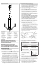
14) Grounding instrucons: (See Illus. a or b).
a) On xtures where mounng strap is provided with a hole
and two raised dimples. Wrap ground wire from outlet
box around green ground screw, and thread into hole.
b) On xtures where a cupped washer is provided. Aach
ground wire from outlet box under cupped washer and
green ground screw, and thread into mounng strap.
If xture is provided with ground wire. Connect xture ground
wire to outlet box ground wire with wire connector (Not
provided) aer following the above steps. Never connect
ground wire to black or white power supply wires.
15) Make wire connecon. Reference chart below for correct
connecons and wire accordingly.
Connect Black or Red
Supply Wire to:
Connect White Supply Wire
to:
Black White
*Parallel cord
(round & smooth)
*Parallel cord
(square & ridged)
Clear, Brown, Gold or Black
without Tracer
Clear, Brown, Gold or Black
with Tracer
Insulated wire (other
than green) with copper
conductor
Insulated wire (other than
green) with silver conductor
*Note: When parallel wire (SPT 1 &
SPT 2) are used. The neutral wire
is square shaped or ridged and the
other wire will be round in shape or
smooth (See illus.)
Neutral Wire
16) Raise canopy to ceiling.
17) Secure canopy in place by ghtening threaded ring onto screw
collar loop.
18) Insert recommended bulbs (Not supplied).
19) Place lower body cap[P] up onto the lower secon of the main
body assembly[O]. Take the nial[Q] and thread into place on
the boom to secure the lower body cap into place.
GREEN GROUND
SCREW
CUPPED
WASHER
OUTLET BOX
GROUND
FIXTURE
GROUND
DIMPLES
WIRE CONNECTOR
OUTLET BOX
GROUND
GREEN GROUND
SCREW
FIXTURE
GROUND
a
b
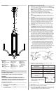
Fixture Diagram
Parts List
[A] Stems
[B] Short Threaded
Tubes
[C] Screw Collar
Loop
[D] Canopy
[E] Strap Mounting
Screws
[F] Outlet Box
[G] Mounting
Strap
[H] Loop
[I] Threaded Ring
[J] Hexnut
[K] Threaded Pipe
[L] Chain Link
[M] Coupler
[N] Body Cap
[O] Main Body
Assembly
[P] Lower Body
Cap
[Q] Finial
Cauons
CAUTION – RISK OF SHOCK –
Disconnect Power at the main circuit breaker panel or main
fusebox before starng and during the installaon.
WARNING:
This xture is intended for installaon in accordance
with the Naonal Electrical Code (NEC) and all local code
specicaons. If you are not familiar with code requirements,
installaon by a cered electrician is recommended.
Installaon Instrucons
1) Rotate arms to the correct posion.
2) Run wires through body cap[N] and place onto main body
assembly[O].
3) Pass wire through the coupler[M] and thread into place on top
of installed body cap.
Installaon Instrucons (connued)
F
G
E
►
C
D
H
L
A
►
►
B
O
N
M
P
Q
K
J
I