Table of contents 1.0 Preface ---------------------------------------------------------------------------------------- 1-1 1-1 Introduction ---------------------------------------------------------------------------- 1-1 1-2 Safety Note and Precaution ---------------------------------------------------------- 1-2 2.
1 Preface 1-1 Introduction DS-C33 series UPS is one of the industry’s most reliable and stable power protection equipment. It is fully controlled by DSP (Digital Signal Processor) to ensure high performance and worry free operation in protecting your valuable equipment from power disturbances. This makes the DS-C33 series UPS fully compatible for use in computer, precision instrument, banking, manufacturing, and other mission critical applications.
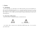
2 System structure 2-1 System Diagram of DS-C33 (12) (5) (7) S6 S2 Utility 2 S3 S5 Utility 1 Load S1 S4 + Battery Pack (1) (2) (3) (4) (13) (6) (8) fig.
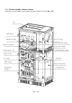
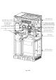
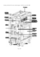
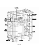
2-2 System assembly and parts layout Drawings 2-2A and 2-2B are the assembly diagrams of DS-C33 series 100K, 120K Fan INV Module Input AC Choke INV/Driver Board AC Power Sensor Board DSP Control Board System Power Board AS-400 Interface Card Communication Port S2/S1 Switch S3 Switch S4 Switch S6/S5 Switch System Transformer Input/Output Terminal S4 Battery Fuse Fig.
DC Capacitance Rectifier/Charger Module Static Switch Control Board Rectifier/Charger Control Board Input Relay Power Board 12 Pluse Power Sensor Board Static Switch Module Fan Input Relay Module DC Choke INV Transformer Fig.
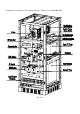
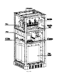
Drawings 2-2C and 2-2D are the assembly diagrams of DS-C33 series 45K, 60K, 80K Fig.
Fig.
Drawings 2-2E and 2-2F are the assembly diagrams of DS-C33 series 22.5K, 30K. Fig.
Fig.
Drawings 2-2G and 2-2H are assembly diagrams of DS-C33 series 10K&15K Fig.
Fig.
2-3 Introduction on function of main module 2-3-1 Rectifier / battery charger (1) Rectifier / battery charger module is using SCR components for transforming AC to DC voltage and to recharge the batteries. (2) In Rectifier / battery charger module, double control method to CPLD and DSP are combined to keep rectifier and battery charger more steady and reliable. (3) Has complete system for protection from over voltage. (4) Detection on phase sequence error or single phasing.
2-3-2 Introduction to inverter module (1) Uses IGBT as power component. (2) Uses high technology DSP to control the inverter module. (3) Utilize digital control management to prevent discrete component from aging, temperature slant and reduce the quantity of parts to enhance system reliability. (4) Integrated A/D signal processing, 12bit resolution and high speed transferring capability.
2-3-4 Input start up/protect trigger (1) Start up function. This function is used for delaying the input power during start up or utility recovery to protect the unit from electrical surge impact. The function is controlled by the main control board. (2) Protection function. This function is used whenever input voltage is too high or too low or wrong phase sequence or if one phase is missing. In this case, the input trigger will be cut to protect the unit.
2-4 System operation mode 2-4-1 System is normal (Fig. 2-4-1) S6 Manual bypass switch AC choke S3 Utility Input switch DC choke S5 Load Input protection Inverter S4 Battery switch Rectifier S1 Battery auxiliary switch - Transformer S.T.S. Output switch + Battery Pack Fig. 2-4-1 Utility AC input supplies the rectifier /battery charger where the AC is converted into DC. Battery is recharged while the DC is fed to the inverter module.
2-4-3 System is powered by battery (fig.2-4-3) S6 Manual bypass switch AC choke S3 Utility Input switch DC choke S5 Load Input protection Inverter S4 Battery switch Rectifier S1 Battery auxility switch - Transformer S.T.S. Output switch + Battery Pack Fig. 2-4-3 In the absence of the utility input, the rectifier stops and DC power is supplied by the batteries to the inverter module. The inverter converts the DC into AC. The static switch connects the inverter output to the load.
2-4-5 EPO switch (fig. 2-4-5) S6 Manual bypass switch AC choke S3 Utility Input switch DC choke S5 Load Input protection Inverter S4 Battery switch Rectifier S1 Battery auxility switch - Transformer S.T.S. Output switch + Battery Pack Fig 2-4-5 Be sure the to check if the EPO is switch otherwise it will not be possible to start up the UPS and no voltage will be supplied to the output load.
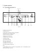
3 Panel function 3-1 Status indication on LED panel (Fig. 3-1 and Fig 3-2) ←Key ↑ Key → Key ↓ Key ESC Key ON Key ENTER Key Fig. 3-1 Fig.
Status indication on LCD/LED panel is divided into 4 modes: (1) System Normal mode: In this mode, only INPUT, RECTIFIER, CHARGE, INVERTER, OUTPUT LEDs are illuminated and others LEDs are off. (2) System Bypass mode: INPUT, BYPASS and OUTPUT LEDs are illuminated and others are off. (3) Back-up mode: DISCHARGE, INVERTER and OUTPUT LEDs are illuminated and others are off. (4) Manual Bypass mode: When Switch S6 is switched to “ON” position, Only MANUAL BYPASS LED is on, others are off.
3-3 LCD Panel description (A-1) Date display MAIN MENU A Date display B Event stories C System set D Time display E Time set I/P V / I/P Freq. I/P I / I/P Cap. / Total Cap. O/P V / O/P Freq. O/P I / O/P Cap. / Total Cap. O/P Power / Load Cap. Bat V, C/C, C/M, Mech. Temp.
(A-1) (A-2-1) Date display I/P V / I/P Freq. I/P I / I/P Cap. / Total Cap. O/P V / O/P Freq. I/P V RS 000.0V RN 000.0V ST 000.0V SN 000.0V TR 000.0V TN 000.0V I/P Freq . : 00.0 HZ O/P I / O/P Cap. / Total Cap. O/P Power / Load Cap. (A-2-2) Bat V, C/C, C/M, Mech. Temp. I/P I (A-2-6) I/P Cap. RN 000.0A 000.00KVA SN 000.0A 000.00KVA TN 000.0A 000.00KVA Total Cap. : 000.00KVA Bat V:DC 000.0V Bat C/C :000.0A Bat C/M:FL Mech. Temp.:00.0Deg (A-2-3) O/P V RS 380.0V RN 220.0V ST 380.0V SN 220.
(C-1) SYSTEM SET Basic set User set NO Please Enter Security Code **** YES (C-3) USER SET 1 2 3 4 5 Alter security NO. Battery test Communication set F. V.
(C-3) USER SET 1 2 3 4 5 Alter security NO. Battery test Communication set F. V. C/C set Other set (C-4-1) ALTER SECURITY NO. Key in old code **** Key in new code **** (C-4-2) BATTERY TEST ▓ □ □ □ 30 Seconds 1 Month 3 Month Test OFF (C -4-4) F. V.
(C-4-2) BATTERY TEST ▓ □ □ □ Waiting 30 Seconds 1 Month 3 Month Test OFF SUCCEED SUCCEED SUCCEED SUCCEED
(C-4-4) F. V.
(C-4-5) OTHER SET 1 Buzzer 2 Backup time 3 Language 4 Model type BUZZER SET 口 Silence 口 Alarm Succeed LANGUAGE SET 口 English 口 Chinese Succeed MODEL SET 口10K 口15K 口22.
(F-1) TIME SET DATE 200*/**/ ** TIME **: **:** Date/Time Set Y/M/D 200*/**/** H M S : : Succeed
4 Placement and installation 4-1 Placement 4-1-1 Transporting The UPS system is composed of the main equipment and battery pack. Therefore be careful when transporting it and handle it following the points listed below. (1) Follow the arrow symbol in the carton for the correct position of the UPS. Don’t turn it upside down or in a slanting position. (2) It is necessary to fasten the system firmly during transportation. (3) When transporting, don’t remove the packaging to reduce impact to the system.
will be installed. 4-2 Installation 4-2-1 Input / Output Specifications System output 50Hz/60Hz 3 wire 3 phase wire 200Vac, 220Vac 50Hz/60Hz 3 phase 4 wire and grounding wire 110/190Vac,115/200Vac,120/208Vac,127/220Vac 220/380Vac,230/400Vac,240/415Vac System output 50Hz/60Hz 3 phase 4 wire and grounding wire 110/190Vac, 115/200Vac, 120/208Vac, 127/220Vac, 220/380Vac, 230/400Vac, 240/415Vac. The table below shows the UPS input/output current and switch specifications. Rating Voltage Input max.
Table 4-2-1 When installing the UPS, please refer to table of 4-2-1 for corresponding input/output circuit breaker.
Table 4-2-2A For wire diameters for different capacity of UPS system, please check the table 4-2-2B below Wire diameter of ground wire 10KVA 8mm2 15KVA 8mm2 22.
4-2-3 Input/Output connection and precaution From table 4-2-1 and table 4-2-2, we could determine the installation wire diameter and breaker capacity, as shown below. Rating Mains voltage Input circuit breaker Input wire diameter (mm2) Output circuit breaker Output wire diameter (mm2) 110/190V 3P/60A 14 3P/50A 14 120/208V 3P/50A 14 3P/40A 14 220/380V 3P/30A 5.5 3P/20A 5.
After wiring, please check the following points listed below. (1) Screws in each point are tight. (2) Ground wire is connected well. (3) No short-circuit in the output switch board and load circuits. (4) Battery fuse switch S4 in switched off. (5) Batteries are connected correctly. (6) All switches of the UPS from S1 to S6 are off. 4-2-4 Precaution for grounding system The grounding mode is divided into 4 categories: (1) Equipment grounding: used in low voltage equipment, grounding by non-charged metal.
Table for battery cable diameter corresponding to capacity of UPS UPS capacity 10KVA 15KVA 22.5KVA 30KVA 45KVA 60KVA 80KVA 100KVA 120KVA Battery cable diameter (mm2) 5.
5 Operation procedure 5-1 Start up procedure 5-1-1 Initial start up procedure (1) Introduction to switches inside the equipment and its function S1 Switch: auxiliary switch S2 Switch: secondary input power switch or BYPASSS switch for the model with input transformer.
(5) 1.Initial start up procedure: Make sure all the loads connected to the UPS are switched off. Turn on Switch S1, S2 and turn off S3 in sequence. Then turn off S4 fuse switch in the UPS. Press the “ON” button on the LCD panel and a screen for confirming setting appears. Press “ ENTER” button. A message “Setting complete” on the screen appears in a few seconds to indicate setting is successful.
Fig.
5-1-2 General start up procedure After the system is initialized successfully and shut down, please follow the steps below to start up the equipment again. Press the “ON” button on the LCD panel and a screen for confirming setting appears. Press on “ENTER” button. Then a message “Setting complete” appears in a few seconds to indicate the setting is okay. BYPASS LED on the front panel will be lit off and INVERTER indicator will be light up in 50 seconds, which indicates UPS is powered by the INVERTER.
Fig.
5-3-2 Procedure for replacing battery (1) Turning off the INVERTER Push “OFF” button on the front panel and then push “ENTER” button to shut down UPS. At that time the UPS enters into maintenance bypass mode. (2) Switching into maintenance bypass mode Turn switch “S6” to “ON” position and put in place its protective cover, and then turn off switch of S5, S4, S3, S2 in sequence (only for some model), switch “S1” (“OFF” position).
5-4 System recovery from maintenance procedure Turn ON switch S1 (for some UPS models only), S2 (for some UPS models only), S3 and S5, Turn off S6 in sequence. Turn on S4 and then press “ON” button on the panel for a few seconds. A screen for conforming setting appears. Press “ ENTER” button. The a message “Setting is successful” will appear in a few seconds. The LCD panel will be illuminated after 50 seconds. Measure the voltage on terminal B+ and B- to see if the value is exact 410VDC.
5-5 Introduction to LCD front panel and illustration of each function Introduction to function keys on the front panel → button: Moves the page cursor to the right ← button: Moves the page cursor to the left OFF button: “OFF” function key ON button: “ON” function key ↑button: Moves up the page cursor ↓button: Moves down the page cursor ENTER button: Execute/confirm setting ESC button: Return to previous page Use →,←,↑,↓ function key to select item on LCD menu and then press ENTER to enter the category you n
6 Maintenance (1) Keep the operating environment clean and clean the inside of the UPS at least once a year. (2) Discharge and charge the battery at least once every three months to improve the life of the battery. (3) Please note the temperature and humidity of the operating environment. (4) When storing the UPS, use PE plastic bag to pack it. (5) Check the lithium cell on the PCB3304 every year and change it if the cell voltage goes under 2 VDC.
7 Specifications for DS-C33 Series UPS Model DS DS DS DS DS DS DS DS 10KC33 15KC33 22.5KC33 30KC33 45KC33 60KC33 80KC33 100KC33 120KC33 Capacity 10KVA 15KVA 22.5KVA 30KVA 45KVA 60KVA 80KVA 100KVA 120KVA Rating Power 8KW 12KW 18KW 24KW 36KW 48KW 64KW 80KW 96KW Power factor AC input DS 0.
Model Physical size DS DS DS DS DS DS DS DS DS 10KC33 15KC33 22.
8 DS-C33 Series troubleshooting 8-1 Simple troubleshooting chart Error message displayed Input over-voltage Input under-voltage Error description Troubleshooting (1)Utility voltage is too high Recover utility to +/-20% or below (2)Ol-3320 detects circuit error Replace ol-3320 (3)Ol-3300 feedbacks circuit error Replace ol-3300 (4)Ol-3300 program parameter is too high Correct program parameter (1)Utility voltage is too low Recover utility to +/-20% or below (2)Ol-3320 detects circuit error Rep
Voltage of DC chain voltage is too high (1)Ol-3302DCvoltage feedbacks point open circuit Recover feedbacks circuit (2)Ol-3302 feedbacks circuit error Replace ol-3302 (3)Ol-3300program parameter is too Correct program parameter high Voltage of DC chain voltage is too low Recharge current is too high Temperature of recharge machine is too high (4)SCR component short circuit Replace SCR component (5)Error on ol-3302 control Replace ol-3302 (1)Ol-3302DCvoltage feedbacks point open circuit Recover
8-2 Simple troubleshooting for Inverter Error message displayed Error description Output over-voltage (1)Ol-3320 detects circuit error Replace Ol-3320 (2)Ol-3300 feedbacks circuit error Replace Ol-3300 (3)Ol-3300 program parameter is too high Correct Program Parameter (4)Ol-3300controlerror Replace Ol-3300 (1)Ol-3320 detects circuit error Replace Ol-3320 (2)Ol-3300 feedbacks circuit error Replace Ol-3300 (3)Ol-3300program parameter is too low Correct Program Parameter (4)Ol-3300controlerror
8-3 Simple troubleshooting for system function Error message displayed Battery can’t supply power Input voltage is lower than 25% Temperature of main machine is overheat Humidity of main machine is too high No second power found No any Power Description Troubleshooting (1)No battery found Add battery (2)Battery power is insufficient Recharge battery (3)Ol-3302 detects circuit error Replace ol-3302 (4)Ol-3300 program parameter inaccuracy Correct program parameter (1)Utility voltage is too low
Battery is in low voltage and UPS is about to be shut down Error on battery test Emergency power functions (1)Input power to low or no utility Recover utility to within+/-20% (2)Battery voltage decreases to low voltage point Unload to 10%~20% of load (3)Ol-3320 detects circuit error Replace ol-3320 (4)Ol-3302 detects circuit error Replace ol-3302 (5)Ol-3300 feedbacks circuit error Replace ol-3300 (6)Error on ol-3300 program parameter Correct program parameter (1)No battery Add battery (2)Ba