
User guide

2 System structure
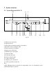
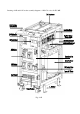
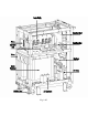
2-1 System Diagram of DS-C33
(12) (5) (7)
Load
Battery
Pack
+
-
S3
S6
S4
S5
S1
Utility 1
Utility 2
S2
(1) (2) (3) (4) (13) (6) (8) (9) (10) (11)
fig. 2-1
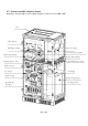
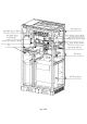
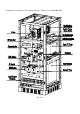
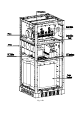
(1) Main power switch (S3)
(2) Input protection
(3) Three phase alternating current power inductor
(4) Rectifier / battery charger module
(5) Direct current power inductor
(6) Battery fuse switch (S4)
(7) Manual bypass switch (S6)
(8) Inverter module
(9) Isolation transformer
(10) Static switch module
(11) Output switch (S5)
(12) Bypass power switch (S2)
(13) Start up auxiliary switch (S1)
Note :
(1)The UPS input can be powered from a single utility source or by dual utility sources.
(2)Dual utility input is optional.