
Owner manual


Chapter 1 Installation
16
Position
Name
Purpose
J4.1
EPO_NC
EPO is activated when disconnecting fromJ4.2
J4.2
+
24V
+24V, connect the common terminal of NC and NO
J4.3
EPO_NO
EPO is activated when shorting with J4.2
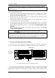
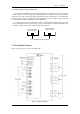
The EPO is triggered when shorting pin 2 and 3 or opening pin 2 and 1 of J4.
If an external emergency stop facility is required, it is connected via the reserved terminals of J4.
The external emergency stop facility needs to use shielded cables to connect to the normally
open/closed remote stop switch between these two pins. If this facility is not used, then pin 3 and pin 4 of
J4 must be open, or pin 1 and pin 2 of J4 must be shorted.
警告
危险
Note
1. The emergency stop action within the UPS will shut down the rectifier, inverter and static bypass.
However, it does not internally disconnect the mains input power supply. To disconnect ALL power to
the UPS, open the upstream input circuit breaker(s) when the EPO is activated.
2. Pin 1 and 2 of J4 have been shorted before the UPS is delivered.
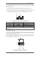
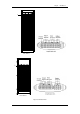
1.7.3 Generator Input Dry Contact
J5 is status interface for generator connection. Connect pin 2 of J5 with + 24V power supply, it
indicates that the generator has been connected with the system. The interface diagram is shown in fig
1-15, and interface description is shown in table 1-5.
J5
GEN
+24V
AUX-N.O.
AUX-N.O.
发电机
Fig 1-15 Diagram of status interface and connection of generator
Table 1-5 Description of maintenance bypass switch and output switch status interface
Position
Name
Purpose
J5.1
+24V
+24V power supply
J5.2
GEN
Connection status of generator
J5.3
GND
Power ground
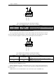
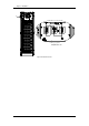
1.7.4 BCB Input Port
J6 and J7 are the ports of BCB. The port diagram is shown in fig 1-16, and description is shown in
table 1-6.
Generator