
Owner manual


Chapter 1 Installation
18
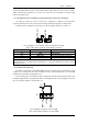
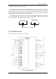
J9
ALARM_NC
ALARM_NO
GND
Fig 1-18 Integrated warning dry contact interface diagram
Table 1-8 Integrated warning dry contact interface description
Position
Name
Purpose
J9.1
ALARM_NC
Integrated warning relay (normally closed) will be open during warning
J9.2
ALARM_NO
Integrated warning relay (normally open) will be closed during warning
J9.3
GND
Centre of integrated warning relay
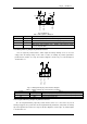
1.7.7 Mains Failure Warning Output Dry Contact Interface
J10 is the output dry contact interface for mains failure warning, when the mains fails, the system
will send a mains failure warning information, and provide an auxiliary dry contact signal via the isolation
of a relay. The interface diagram is shown in fig 1-19, and description is shown in table 1-9.
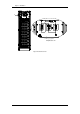
J10
UTI_FAIL_NC
UTI_FAIL_NO
GND
Fig 1-19 Mains failure warning dry contact interface diagram
Table 1-9 Mains failure warning dry contact interface description
Position
Name
Purpose
J9.1
UTI_FAIL_NC
Mains failure warning relay(normally closed) will be open during
warning
J9.2
UTI_FAIL_NO
Mains failure warning relay (normally open) will be closed during
warning
J9.3
GND
Centre of mains failure warning relay
1.7.8 RS232 Port and SNMP Card Port
RS232 and RS485 Port: provide serial data which can be used for commissioning and maintenance
by authorized engineers or maintainers, or can be used for networking or integrated monitoring system in
the service room.
SNMP Card Port: used for field installation of the communication option card(SNMP card).