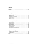
CONTENTS Introduction . . . . . . . . . . . . . . . . . . . . . . . . . . . . . . . . . . . . . . . . . . . . . . . . . . . . . . .2 Practice Safe Sound™ . . . . . . . . . . . . . . . . . . . . . . . . . . . . . . . . . . . . . . . . . . . . . . .2 Limited Two-Year Consumer Warranty . . . . . . . . . . . . . . . . . . . . . . . . . . . . . . . . . .3 Record Your Serial Number and Date . . . . . . . . . . . . . . . . . . . . . . . . . . . . . . . . . . . . .3 Specifications . . . . . . . . . . . . . . . . .
INTRODUCTION Thank you for your purchase of Orion's 4002 or 6002 amplifier. Each Orion amplifier is designed to be the leader in its class offering the most power, advanced features, and ease of use. Orion amplifiers are designed as the best affordable high end car audio amplifier money can buy. Listed below are the features of the new Orion 4002 and 6002.
LIMITED TWO-YEAR CONSUMER WARRANTY Directed Electronics, Inc. promises to the original purchaser, to replace this product should it prove to be defective in workmanship or material under normal use, for a period of two years from the date of purchase by the dealer as indicated by the date code marking of the product PROVIDED the product was installed by an authorized Directed dealer.
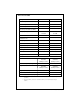
SPECIFICATIONS Amplifier Section Orion 4002 Orion 6002 Power Output 4W Stereo (Watts)1 100 x 2 150 x 2 Power Output 2W Stereo (Watts)2 200 x 2 300 x 2 Power Output 4W Mono (Watts) 400 x 1 600 x 1 Distortion with all channels driven at rated power (20Hz to 20kHz) < 0.1% THD+N < 0.1% THD+N Frequency Response 20Hz to 20kHZ ±0.25dB 20Hz to 20kHZ ±0.
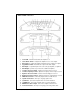
END PANEL LAYOUT 1. Power LED - when lit indicates that the amplifier is on. 2. Stereo/Mono Switch - configures the amplifier for one or two inputs. 3. Gain Control - continuously adjusts from 200mV to 5V for full power output. 4. Copy/Master Switch - Determines the output of the RCA outputs. 5. RCA Inputs - accepts RCA input from a source unit, preamplifier, or equalizer. 6. RCA Outputs - provides easy connection to additional amplifiers. 7.
Stereo / Mono Input Configuration The STEREO / MONO switch routes input from the front inputs to the rear section of the amplifier. This allows the Orion 4002 and 6002 amplifiers to utilize a single RCA or highlevel input to feed signal to both the right and left channels of the amplifier. When the switch is to the right (MONO position), signal from the left input is routed to the right channel. When the switch is to the left (STEREO position), right and left inputs are independent.
High-Pass Crossover When the switch is to the right (OFF position), the high-pass crossover is bypassed. When the switch is to the left (ON position), the high-pass crossover is active. The high-pass crossover is continuously variable from 20Hz to 3kHz. High-Pass Woofers The high-pass crossover is continuously variable from 20Hz to 3kHz. The high-pass crossover is now optimized for use as a subsonic filter for subwoofers.
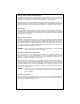
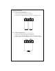
Speaker Connections Two-Channel Stereo Configuration ● Lowest recommended impedance is 2W stereo. ● Stereo input should be used for this configuration. ● Outputs can be configured for high-pass, low-pass, or full range operation. Mono Bridged Configuration 8 ● Lowest recommended impedance is 4W bridged mono. ● Mono or stereo input can be used for this configuration. ● Outputs can be configured for high-pass, low-pass, or full range operation.
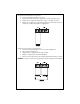
Single-Channel Bridged Configuration ● Lowest recommended impedance is 4W mono. ● Mono input must be used for this configuration. Only the Left input is used. ● Outputs can be configured for high-pass, low-pass, or full range operation. ● Outputs are configured for single-channel bridged operation which is ideal for separate left or right channel subwoofer applications. Tri-Mode Three-Channel Configuration ● Lowest recommended impedance is 2W stereo and 4W bridged mono.
AMPLIFIER INSTALLATION Choosing Mounting Locations The location of your amplifier will depend on several important issues. Due to the low profile size of the Orion amplifiers, there are many possible installation locations that will yield satisfactory amplifier performance. Always mount the amplifier in a place that protects the amplifier from the elements. In addition, mount the amplifier on a stable, flat surface.
Power for systems with a single amplifier can be supplied by most automotive electrical systems. Systems with multiple amplifiers may require a higher capacity battery, alternator or the use of a storage capacitor. We strongly recommend the use of a Directed Audio Essentials power capacitor with an extra battery in larger stereo systems. Orion amplifiers generate a certain amount of heat as part of normal operation. Be sure the area around the amplifier is unobstructed to allow adequate air circulation.
amplifier is twisted or bent. Step 6 Turn the vehicle's key switch to the off position. Step 7 Disconnect the vehicle's battery ground terminal. Step 8 Connect power wires to the amplifier (ground first, then 12 V(+) and RGC). Step 9 Connect the RCA and speaker wires to the amplifier. Check the quality of your speakers and signal connections. This will determine the ultimate performance of your Orion amplifier.
Adjusting the Sound of the System Once you have checked the system's operation, adjust the sound of the system. Adjusting the sound of the system is accomplished by setting the level controls and adjusting the internal crossovers. Step 1 Turn the signal source volume control all the way down. Set any tone controls to their flat or defeated positions. This includes the loudness control. Step 2 Turn the level controls of the amplifier to their minimum positions.
Troubleshooting Tips Symptom Probable Cause Action To Take Low or no remote turn-on Check remote turn-on voltage at voltage amplifier and repair as needed. Fuse blown Check power wire's integrity and check for speaker shorts. Fix as needed and replace fuse. No output Power wires not connected Check power wire and ground connections and repair or replace as needed. Audio input not connected Check RCA connections and repair or replace as needed.
Symptom Probable Cause Action To Take Internal crossover not set properly for speakers Readjust crossovers. Refer to the Internal Crossover Configuration section of this guide for detailed instructions. Speakers are blown Check system with known work ing speakers and fix or replace as needed. Distorted output Poor bass response Speakers wired with wrong Check speaker polarity and fix polarity causing cancellation as needed. at low frequencies Crossover set incorrectly Reset crossovers.
NOTES ____________________________________________________ ____________________________________________________ ____________________________________________________ ____________________________________________________ ____________________________________________________ ____________________________________________________ ____________________________________________________ ____________________________________________________ ____________________________________________________ _____________________________
Warranty LIMITED TWO YEAR CONSUMER WARRANTY: Directed Electronics, Inc. promises to the original purchaser, to replace this product should it prove to be defective in workmanship or material under normal use, for a period of two years from the date of purchase by the dealer as indicated by the date code marking of the product PROVIDED the product was installed by an authorized Directed dealer.