CONTENTS Intorduction . . . . . . . . . . . . . . . . . . . . . . . . . . . . . . . . . . . . . . . . . . . . . . . . . . . . . . .2 What’s in the Box . . . . . . . . . . . . . . . . . . . . . . . . . . . . . . . . . . . . . . . . . . . . . . . . . . . . .2 Practise Safe Sound™ . . . . . . . . . . . . . . . . . . . . . . . . . . . . . . . . . . . . . . . . . . . . . . .2 Warranty . . . . . . . . . . . . . . . . . . . . . . . . . . . . . . . . . . . . . . . . . . . . . . . . . . . . . . . . . .
INTORDUCTION Thank you for your purchase of Orion's 7005 amplifier. Each Orion amplifier is designed to be the leader in its class offering ease of use, advanced features, and the most power. Orion amplifiers are designed as the best affordable high end car audio amplifier money can buy. Listed below are the features of the new Orion 7005. ● 7005 - 50 Watts per four channels and 150 Watts per subwoofer channel, 5-channel amplifier.
WARRANTY Directed Electronics, Inc. promises to the original purchaser, to replace this product should it prove to be defective in workmanship or material under normal use, for a period of two years from the date of purchase by the dealer as indicated by the date code marking of the product PROVIDED the product was installed by an authorized Directed dealer. During this two year period, there will be no charge for this replacement PROVIDED the unit is returned to Directed, shipping pre-paid.
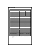
SPECIFICATIONS Amplifier Section Front and Rear Channels Subwoofer Channel Power Output 4W stereo (Watts)1 50 x 4 N/A Power Output 2W stereo (Watts)2 100 x 4 N/A Power Output 4W mono (Watts)1 200 x 2 150 x 1 Power Output 2W mono (Watts)2 N/A 300 x 1 Remote Gain No Yes Distortion - with all channels driven at rated power (20Hz to 20kHz) Frequency Response < 0.1% THD+N 20Hz to 20kHz ±0.
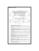
END PANEL LAYOUT 1. Power LED - indicates that the amplifier is on. 2. Front Low-Pass Crossover Switch - activates 2nd order low pass crossover. 3. Front Low-Pass Frequency Control - adjusts the frequency of the low-pass crossover. 4. Front Gain Control - continuously adjusts from 200mV to 5V for full power output. 5. Front High-Pass Crossover Switch - activates 2nd order high pass crossover. 6. Front High-Pass Frequency Control - adjusts the frequency of the high-pass crossover. 7.
18. Subwoofer Low-Pass Crossover Switch - activates 2nd or 4th order low pass crossover. 19. Subwoofer Low-Pass Frequency Control - adjusts the frequency of the lowpass crossover. 20. Subwoofer High-Pass Crossover Switch - activates 2nd order high pass crossover. 21. Subwoofer High-Pass Frequency Control - adjusts the frequency of the highpass crossover. 22. INTELLi Q Control - continuously adjusts from 0 to 10dB of boost. 23. Speaker Connections - allow up to 12-gauge speaker wire. 24.
When using Orion loudspeakers, minor deviations from the recommended frequency ranges can provide superior results depending on your speaker locations and your vehicle acoustics. Setting crossover frequencies higher than recommended will not cause damage and may provide superior sonic results depending on your system's performance goals. Refer to your loudspeaker owner's manual for assistance in choosing the proper crossover frequencies for your system.
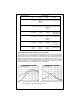
Enclosure Type Boost Levels +6dB 0dB +3dB +10dB Infinite Baffle Tune above Fs of woofer High X-Max Drivers--Tune above Fs of woofer Not Not Recommended Recommended Sealed Tune above Fs of woofer Tune above Fs of woofer High X-Max Drivers--Tune above Fs of woofer Not Recommended Vented Tune to port frequency Tune to port frequency Tune to port frequency High X-Max Drivers--Tune to port frequency Sealed Band-pass Tune above Fs of woofer Tune above Fs of woofer High X-Max Drivers--Tune ab
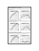
Sealed Example High-Pass Set at 20Hz This sealed example is the same 12-inch woofer in the recommended sealed enclosure. Up to 6 dB of boost is capable if 20 Hz was used. With +6dB of boost, the woofer has more output down to 15 Hz. Sealed Example High-Pass Set at 30Hz In this example, the frequency has been increased to 30 Hz. Up to 6 dB of boost is capable at this frequency. With +6dB of boost, the woofer has more output down to 23 Hz. The overall usable output is increased.
Remote Gain Operation The remote gain port provides easy remote access to the internal gain structure of the subwoofer section of the Orion 7005 amplifier. The RGC-1 plugs into the amplifier via the 1/8" mini jack plug. It can be installed in the front of the vehicle to control the amplifier gain level, and can be used as a bass level control on the subwoofer channel of the Orion 7005.
Three Channel Bridged Stereo Configuration ● Front and rear channels are configured for bridged two-channel operation ● Lowest recommended impedance for both front and rear channels is 4W ● Crossover and gain configurations are independently adjustable between the front, rear, and subwoofer channels. ● Two-channel operation is recommended for this operational mode. ● Front and rear outputs can be configured for high-pass, low-pass, band-pass, or full range operation.
AMPLIFIER INSTALLATION Choosing Mounting Locations The location of your amplifier will depend on several important issues. Due to the low profile size of the Orion amplifiers, there are many possible installation locations that will yield satisfactory amplifier performance. Always mount the amplifier in a place that protects the amplifier from the elements. In addition, mount the amplifier on a stable, flat surface.
Power for systems with a single amplifier can be supplied by most automotive electrical systems. Systems with multiple amplifiers may require a higher capacity battery, alternator or the use of a storage capacitor. We strongly recommend the use of a Directed Audio Essentials power capacitor with an extra battery in larger stereo systems. Orion amplifiers generate a certain amount of heat as part of normal operation. Be sure the area around the amplifier is unobstructed to allow adequate air circulation.
Step 6 Turn the vehicle's key switch to the off position. Step 7 Disconnect the vehicle's battery ground terminal. Step 8 Connect power wires to the amplifier (ground first, then 12 V(+) and RGC). Step 9 Connect the RCA and speaker wires to the amplifier. Check the quality of your speakers and signal connections. This will determine the ultimate performance of your Orion amplifier.
Adjusting the Sound of the System Once you have checked the system's operation, adjust the sound of the system. Adjusting the sound of the system is accomplished by setting the level controls and adjusting the internal crossovers. Step 1 Turn the signal source volume control all the way down. Set any tone controls to their flat or defeated positions. This includes the loudness control. Step 2 Turn the level controls of the amplifier to their minimum positions.
Troubleshooting Tips Symptom Probable Cause Action To Take Low or no remote turn-on Check remote turn-on voltage at voltage amplifier and repair as needed. Fuse blown Check power wire's integrity and check for speaker shorts. Fix as needed and replace fuse. No output Power wires not connected Check power wire and ground connections and repair or replace as needed. Audio input not connected Check RCA connections and repair or replace as needed.
Symptom Probable Cause Action To Take Internal crossover not set properly for speakers Readjust crossovers. Refer to the Internal Crossover Configuration section of this guide for detailed instructions. Speakers are blown Check system with known work ing speakers and fix or replace as needed. Distorted output Poor bass response Speakers wired with wrong Check speaker polarity and fix polarity causing cancellation as needed. at low frequencies Crossover set incorrectly Reset crossovers.
NOTES ____________________________________________________ ____________________________________________________ ____________________________________________________ ____________________________________________________ ____________________________________________________ ____________________________________________________ ____________________________________________________ ____________________________________________________ ____________________________________________________ _____________________________
©2003 Directed Electronics, Inc.
20 ©2003 Directed Electronics, Inc.
Warranty LIMITED TWO YEAR CONSUMER WARRANTY: Directed Electronics, Inc. promises to the original purchaser, to replace this product should it prove to be defective in workmanship or material under normal use, for a period of two years from the date of purchase by the dealer as indicated by the date code marking of the product PROVIDED the product was installed by an authorized Directed dealer.