
Installation Manual
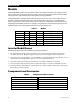
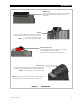


Table of Contents
4 900-0168-01-00 Rev C
List of Tables
Table 1 Models ................................................................................................................................................................. 6
Table 2 Components and Accessories .................................................................................................................... 6
Table 3 Battery Bank Elements .................................................................................................................................12
Table 4 Ground Conductor Size and Torque Requirements .........................................................................18
Table 5 DC Conductor Size and Torque Requirements ...................................................................................20
Table 6 Terms and Definitions .................................................................................................................................41
List of Figures
Figure 1 FXR Series Inverter/Charger ........................................................................................................................ 5
Figure 2 Components ..................................................................................................................................................... 7
Figure 3 Applications (Example) ................................................................................................................................. 9
Figure 4 Dimensions ......................................................................................................................................................16
Figure 5 Terminals, Ports, and Features ..................................................................................................................17
Figure 6 DC Ground Lug ..............................................................................................................................................19
Figure 7 Chassis Ground/PE ........................................................................................................................................19
Figure 8 Required Order of Battery Cable Hardware .........................................................................................21
Figure 9 Battery Terminal Covers ..............................................................................................................................21
Figure 10 DC Cover Attachment ..................................................................................................................................22
Figure 11 Turbo Fan Wiring ...........................................................................................................................................22
Figure 12 AC Terminals ...................................................................................................................................................23
Figure 13 AC Sources .......................................................................................................................................................24
Figure 14 AC Sources and Transfer Relay .................................................................................................................24
Figure 15 ON/OFF Jumper and Connections ..........................................................................................................25
Figure 16 Accessory Connections ...............................................................................................................................25
Figure 17 AUX Connections for Vent Fan (Example) ............................................................................................26
Figure 18 AUX Connections for Diversion (Example) ...........................................................................................26
Figure 19 Two-Wire Generator Start (Example) .....................................................................................................27
Figure 20 Three-Wire Generator Start (Example) ..................................................................................................28
Figure 21 Single-Inverter Wiring
..................................................................................................................................29
Figure 22 OutBack HUB10.3 and MATE3 ..................................................................................................................30
Figure 23 Example of Parallel Stacking Arrangement (Three Inverters) .......................................................31
Figure 24 Parallel Wiring (Four Inverters) .................................................................................................................32
Figure 25 Example of Three-Phase Stacking Arrangement (Three Inverters) .............................................33
Figure 26 Example of Three-Phase Stacking Arrangement (Nine Inverters) ...............................................33
Figure 27 Three-Phase Wiring (Three Inverters) ....................................................................................................35