Radian Series Inverter/Charger GS7048E GS3548E Installation Manual
About OutBack Power Technologies OutBack Power Technologies is a leader in advanced energy conversion technology. OutBack products include true sine wave inverter/chargers, maximum power point tracking charge controllers, and system communication components, as well as circuit breakers, batteries, accessories, and assembled systems.
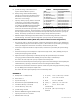
Table of Contents Introduction ................................................................................................. 3 Audience ................................................................................................................................................................................. 3 Welcome to OutBack Power Technologies ................................................................................................................. 3 Components and Accessories ...........
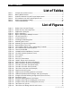
Table of Contents List of Tables Table 1 Table 2 Table 3 Table 4 Table 5 Table 6 Components and Accessories ....................................................................................................... 4 Battery Bank Elements ..................................................................................................................... 8 Ground Conductor Size and Torque Requirements ........................................................... 19 DC Conductor Size and Torque Requirements....
Introduction Audience This book provides instructions for the physical installation and wiring of this product. These instructions are for use by qualified personnel who meet all local and governmental code requirements for licensing and training for the installation of electrical power systems with AC and DC voltage up to 600 volts. This product is only serviceable by qualified personnel. Welcome to OutBack Power Technologies Thank you for purchasing the OutBack Radian Series Inverter/Charger.
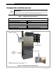
Introduction Components and Accessories IMPORTANT: This product is not compatible with the OutBack MATE or MATE2 System Display and Controller. Use of these products is not supported with the Radian Series.
Planning Applications The Radian Series Inverter/Charger is intended for both off-grid and grid-interactive (Grid/Hybrid) applications. It is designed to use a battery bank to store energy. It can work in conjunction with photovoltaic (PV) panels to harvest solar energy, as well as wind turbines and other renewable sources. These sources charge the battery, which in turn is used by the inverter. The Radian inverter has two sets of AC input terminals.
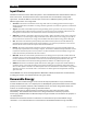
Planning Input Modes The Radian inverter has seven modes of operation. These modes determine how the Radian interacts with an AC source. Each mode has functions and priorities that are intended for a designated application. Each of the Radian’s two AC inputs can be set to a different operating mode, so that different applications can be supported. Generator: This mode is intended for a wide range of AC sources, including generators with a rough or imperfect AC waveform.
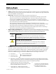
Planning Battery Bank When planning a battery bank, consider the following: Cables: Recommendations for battery cable size and length are shown on page 20. The maximum length will determine the placement of the battery bank. Other local codes or regulations may apply and may take priority over OutBack recommendations. Battery Type: The Radian inverter/charger uses a three-stage charge cycle. ~ The cycle was designed for lead-chemistry batteries intended for deep discharge.
Planning G. System DC voltage: The Radian inverter requires nominal 48 Vdc to operate. H. Battery voltage: Most individual battery voltages are less than the system DC voltage. The batteries need to be placed in series to deliver the correct voltage. Table 2 Battery Bank Elements Item A. Load Size B. Daily Hours C. Days of Autonomy D. Application E. Conductor Efficiency F. Inverter Efficiency G. System Vdc H. Battery Vdc I. Capacity J.
Planning EXAMPLE #2 A. Backup loads: 1.75 kW (1750 W) B. Hours of use: 8 C. Days of autonomy: 2 D. Off-grid system (GS3548E inverter) 1) A ÷ [E x F] 1750 ÷ (0.97 x 0.92) = 1961.0 W 2) 1 ÷ G 1961.0 ÷ 48 = 40.9 Adc 3) 2 x B 40.9 x 8 = 326.8 Ahr E. Conductor efficiency: 97% (0.97) 4) [3 x C] ÷ J [326.8 x 2] ÷ 0.5 = 1307.3 Ahr F. Inverter efficiency: 92% (0.92) 5) 4 ÷ I 1307.3 ÷ 167.5 = 7.8 (rounded to 8) 6) [G ÷ H] x 5 [48 ÷ 12] x 8 strings = 32 batteries G. System voltage: 48 Vdc H.
Planning Maintenance Bypass Switching Inverter systems are often equipped with AC maintenance bypass switches or interlocks. If the inverter system ever needs to be shut down or removed, the AC sources and loads must be disconnected. A bypass device allows the AC source to deliver power directly to the loads, bypassing the inverter. This can minimize disruption to the system and avoids the need for extensive rewiring.
Installation Location and Environmental Requirements Radian Series Inverter/Chargers must be located in a weather-proof enclosure or enclosed area. It is not designed for exposure to water or excessive wind-blown dust and debris. It carries an Ingress Protection (IP) rating of 20 and a Relative Humidity (RH) rating of 93%. The Radian inverter must be wall-mounted in an upright position. The inverter is not approved for mounting in any other position or orientation.
Installation 1.1 cm (0.45") 1.1 cm (0.45") 22.2 cm (8.75”) Width 40.6 cm (16") 34.8 cm (13.7”) 71.1 cm (28”) 73.7 cm (29.0”) 114.3 cm (45.0”) 31.8 cm (12.5”) 35.6 cm (14.0") Figure 7 12 This illustration can be used as a basic template for planning layouts, marking mounting holes, etc. when installing a system. The requirements for mounting the Radian inverter are described beginning on the next page.
Installation Tools Required The following tools may be required for this installation: Wrench and socket sets; should include torque and ratchet wrenches; also reversible (stubby) wrenches for narrow access Insulated screwdriver set; should include a #2 Phillips screwdriver 38 to 41 cm long Wire cutters/strippers Long-nose pliers DVM or voltmeter Mounting Two or more people may be needed to install the Radian inverter/charger due to its weight.
Installation …continued from the previous page… 2. Radian Inverter Place the Radian inverter against the wall and slide it directly over the upper lip of the mounting plate. The inverter’s mounting flange should come to rest within the lip so that it hangs securely. To assist in alignment, dimples have been placed on the side of the unit to mark the lower edge of the flange. In the picture to the left, the two X symbols show the location of the dimples. xx Mounting Plate 3.
Installation Component Mounting The top of the GS Load Center (GSLC) connects to the bottom of the Radian inverter using four keyhole slots. The keyhole slots fit over four screws on the bottom of the inverter that secure the GSLC to the inverter when they are tightened. (The long screwdriver recommended on page 13 may be needed to reach these screws.) The GSLC should be secured to the wall using screws or wall anchors.
Installation Removing Front Cover The front cover must be removed in order to access the Radian inverter’s AC terminals and other connections. These include the Remote and Batt Temp ports, as well as several sets of auxiliary terminals. Twenty-two machine screws are located around the perimeter. Remove these screws with a #2 Phillips screwdriver. Once they are removed, the cover can be lifted off. NOTE: The screws which secure the plastic plates to the cover do not need to be removed.
Installation Terminals and Ports DC TERMINALS Connects to the battery cables and DC system. There are two DC positive and two DC negative terminals. Each DC positive terminal requires separate cables and separate overcurrent protection. See page 20 for instructions. RIBBON CABLES Connects the Radian’s power modules and control board. See Warning below. ON/OFF INV JUMPER (J3): Overrides the SWITCH INV terminals when installed. When installed, the inverter is ON.
Installation CONTROL WIRING TERMINAL BLOCK: Receives control wires for a variety of functions, including generator control. See facing page for terminal descriptions. REMOTE and BATTERY TEMP PORTS: Receive the RJ45 and RJ11 plugs from the MATE3 system display and Remote Temp Sensor. See page 24 for instructions. AC TERMINAL BLOCK Receives AC input wires for two input sources. Also receives AC output wires. All neutral wires are electrically common. See page 22 for instructions.
Installation Wiring It will be necessary to remove knockouts from the chassis to run wires. Bushings are included with the hardware kit to protect the wires. Make sure to install these bushings in the holes. Use copper wire only. Wire must be rated at 75°C or higher. Grounding WARNING: Shock Hazard This unit meets the IEC requirements of Protection Class I. The unit must be connected to a permanent wiring system that is grounded according to the IEC 60364 TN standard.
Installation DC Wiring WARNING: Shock Hazard Use caution when working in the vicinity of the inverter’s battery terminals. CAUTION: Equipment Damage Never reverse the polarity of the battery cables. Always ensure correct polarity. CAUTION: Fire Hazard The installer is responsible for providing overcurrent protection. Install a circuit breaker or overcurrent device on each DC positive (+) conductor to protect the DC system.
Installation Table 4 Inverter DC Conductor Size and Torque Requirements Nominal DC Amps Conductor Size (Minimum, per breaker) (Derated 125%) (Minimum, per breaker) 91 91 70 mm2 or 2/0 AWG (0.105 in2) 70 mm2 or 2/0 AWG (0.105 in2) GS7048E GS3548E Terminal Location Breaker Size 175 Adc/AIC 10kA 175 Adc/AIC 10kA Torque Requirements Inverter DC Terminals Battery Terminals 6.
Installation AC Wiring WARNING: Shock Hazard Ensure there is no more than one AC neutral-ground bond at any time. Local or national codes may require the bond at the main panel only. The GSLC is equipped with its own bond, which may need to be removed. IMPORTANT: The installer is responsible for providing overcurrent protection. The AC input and output must be protected with branch-rated circuit breakers of up to 50 Aac maximum size to meet local code requirements.
Installation A Ground Terminal Bus Bar (TBB) is also available if multiple ground connections are needed (see Figure 14 on page 19). WARNING: Shock Hazard During an error shutdown, the inverter’s output terminals are not live. However, if the inverter recovers from a shutdown, the terminals will become live without notice. Several error shutdowns can be recovered automatically, including Low Battery V, High Battery V, and Over Temperature.
Installation Accessory Wiring System Display port RTS port The upper board has ports for both the Remote Temperature Sensor (RTS) and the system display. The system display port is labeled Remote. The RTS port is labeled Battery Temp. If a HUB Communications Manager is in use, it occupies the inverter’s Remote port. The system display plugs into the HUB product.
Installation AUX Wiring The Radian inverter has two sets of terminals which can respond to different criteria and control many functions. These include cooling fans, vent fans, load diversion, fault alarms, and the Advanced Generator Start (AGS) function. The 12V AUX terminals are a switched 12 Vdc power supply. They can control any of the Auxiliary Output functions available in the MATE3. The 12V AUX terminals can supply up to 0.7 amps at 12 Vdc (8.4 watts).
Installation In this example, the 12V AUX terminals drive a relay that diverts wind power. The relay’s coil is connected to the 12V AUX terminals. When the AUX function closes the relay (based on battery voltage), the relay diverts the excess wind power to a water heating element. Turbine Relay NOTE: Relays and elements shown are examples only and may vary depending on the installation.
Installation In other cases, or in the case of a three-wire-start generator, the inverter should use the 12V AUX terminals instead, in conjunction with a three-to-two wire converter. (See pages 27 and 28.) RELAY AUX Terminals Two-Wire-Start Generator Starting Switch Figure 23 Two-Wire Generator Start (RELAY AUX) Two-Wire-Start (12V AUX Terminals) The 12 Vdc signal provided by the 12V AUX terminals can be switched on and off to provide a start signal.
Installation Three-Wire-Start A “three-wire-start” generator has two or more starting circuits. It usually has a separate switch or position for cranking the generator. A three-wire generator has fewer automated functions than a two-wire. It usually requires multiple controls for starting, running, or stopping. The inverter terminals cannot control this type of generator without using a three-wire to two-wire conversion kit. Atkinson Electronics (http://atkinsonelectronics.
Installation AC Configurations Single-Inverter Figure 26 (below) shows the general wiring of the Radian inverter and the AC system connected to it. This figure is not a physical representation of the inverter and does not depict the GSLC. Figure 27 (see next page) shows the locations of AC and network connections. This figure is a physical diagram for wiring the GSLC, network components, and external AC devices with the inverter.
Installation NOTES: 1. Ground wiring is not shown for reasons of simplicity. Regardless, this system must be connected to a grounded, permanent wiring system. See page 19. 2. The Radian inverter has separate neutral connections for grid input, generator input, and output. These are electrically common. If an external neutral bus exists (as shown in the GSLC), not all of the Radian neutral connections need to be made. In this example, only the Grid neutral terminal on the inverter is connected. 3.
Installation Multiple-Inverter AC Installations (Stacking) Installing multiple inverters in a single AC system supports larger loads than a single inverter can handle. This requires stacking. Stacking refers to how the inverters are wired within the system and then programmed to coordinate activity. Stacking allows all units to work together as a single system. The GS3548E and GS7048E models can stack up to ten units in parallel. For three-phase output, up to nine models can be stacked, three per phase.
Installation Connect all units other than the master to ports 2 and above on the communications manager. The system display may have other port restrictions pertaining to stacking. In general, it is always important to keep track of units and ports for programming purposes. Programming involves using the system display to assign a status and stacking value to the inverter on each port. The stacking assignments can be changed at any time as long as the master is connected to port 1.
Installation Parallel Stacking (Dual-Stack and Larger) In parallel stacking, two or more inverters are stacked to create a single, common AC bus as shown in Figure 29. The slave outputs are controlled directly by the master and cannot operate independently. All inverters share a common input (AC source) and run loads on a common output. Slave inverters can go into Power Save mode when not in use. The master will activate individual slaves based on load demand.
Installation NOTES: 1. The Radian inverter has separate neutral connections for grid input, generator input, and output. These are electrically common. If an external neutral bus exists (as shown in the AC Load Panel above), not all of the Radian neutral connections need to be made. 2. Maintenance bypass switching assemblies are commonly used so that the inverter can be taken offline, if necessary, without shutting down the entire system.
Installation NOTES: 1. Ground wiring is not shown for reasons of simplicity. Regardless, this system must be connected to a grounded, permanent wiring system. See page 19. 2. The Radian inverter has separate neutral connections for grid input, generator input, and output. These are electrically common. If an external neutral bus exists (as shown in the GSLC), not all of the Radian neutral connections need to be made. In this example, only the Grid neutral terminal on each inverter is connected. 3.
Installation Three-Phase Stacking In three-phase stacking, three or more inverters are stacked to create three 230 Vac outputs (or equivalent voltage) in a wye configuration as shown below.
Installation The three outputs operate independently of each other. Each can run in independent Search mode if desired. This does not normally occur when three-phase loads are connected. The output of each inverter is 120° out of phase from the others. Any two outputs produce 400 Vac between them. The outputs can be used to power three-phase loads when all inverters work together. Up to nine inverters, three per phase, may be installed in a three-phase arrangement.
Installation NOTES: 1. The Radian inverter has separate neutral connections for grid input, generator input, and output. These are electrically common. If an external neutral bus exists (as shown in the AC Load Panel above), not all of the Radian neutral connections need to be made. 2. Maintenance bypass switching assemblies are commonly used so that the inverter can be taken offline, if necessary, without shutting down the entire system.
Installation NOTES: 1. Ground wiring is not shown for reasons of simplicity. Regardless, this system must be connected to a grounded, permanent wiring system. See page 19. 2. Only one source (grid) is shown here for reasons of simplicity. The Radian inverter has connections for two AC input sources and can be wired accordingly, although the inverter can only accept one source at a time. 3. The Radian inverter has separate neutral connections for grid input, generator input, and output.
Installation Functional Test Once the mounting, wiring, and other installation steps are completed, proceed to the Radian Series Inverter/Charger Operator’s Manual. The Operator’s Manual has steps for system commissioning. These include powering up and performing a functional test on the inverter system, as well as powering down and adding new devices to an existing system.
Symbols, Terms, and Definitions Symbols Used WARNING: Hazard to Human Life This type of notation indicates that the hazard could be harmful to human life. CAUTION: Hazard to Equipment This type of notation indicates that the hazard may cause damage to the equipment. IMPORTANT: This type of notation indicates that the information provided is important to the installation, operation and/or maintenance of the equipment.
Terms and Definitions Table 6 Terms and Definitions Term Definition EPO Emergency Power Off; a switching product used for emergency shutdown GFDI Ground Fault Detector Interruptor; a safety device for PV systems GND Ground; a permanent conductive connection to earth for safety reasons; also known as Chassis Ground, Protective Earth, PE, Grounding Electrode Conductor, and GEC Grid/Hybrid™ System technology which optimizes both grid-interactive and off-grid options Grid-interactive, grid-intertie, g
Index A E AC Inputs ........................................................... 5, 18, 22, 23 AC Wiring ...................................................................... 18, 22 Advanced Generator Start (AGS) ..................................25 Applications .......................................................................... 5 AS4777 ..................................................................................40 Audience .....................................................................
Index M Maintenance Bypass.........................................................10 Maintenance Checks ........................................................40 MATE and MATE2 ................................................................ 4 MATE3 ................................................................ 4, 15, 18, 42 AUX ...................................................................................25 Stacking...........................................................................
THIS PAGE INTENTIONALLY LEFT BLANK.
Masters of the Off-Grid.™ First Choice for the New Grid. Corporate Headquarters 17825 – 59th Avenue N.E. Suite B Arlington, WA 98223 USA +1.360.435.6030 900-0144-01-01 Rev B European Office Hansastrasse 8 D-91126 Schwabach, Germany +49.9122.79889.