
Installation Guide

Installation
900-0144-01-01 Rev B 29
AC Configurations
Single-Inverter
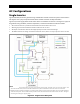
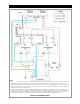
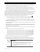
Figure 26 (below) shows the general wiring of the Radian inverter and the AC system connected to it.
This figure is not a physical representation of the inverter and does not depict the GSLC.
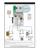
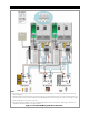
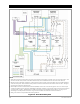
Figure 27 (see next page) shows the locations of AC and network connections. This figure is a physical
diagram for wiring the GSLC, network components, and external AC devices with the inverter.
All overcurrent devices in permanent installations must be sized for 50 Aac or less.
All wiring in permanent installations must be sized for 50 Aac or more.
All output circuit breakers must be sized appropriately for loads and inverter wattage.
The Radian inverter has wiring connections for two AC sources, but it can only accept one source at a time.
Figure 26 Single-Inverter AC System
1. The Radian inverter has separate neutral connections for grid input, generator input, and output. These are electrically common. If an
external neutral bus exists (as shown in the AC Load Panel above), not all of the Radian neutral connections need to be made.
2. Maintenance bypass switching assemblies are commonly used so that the inverter can be taken offline, if necessary, without shutting
down the entire system. These assemblies usually include an interlock mechanism that isolates AC lines from each other. This figure
shows the
g
eneral desi
g
n of a b
yp
ass s
y
stem.
NOTES: