
Installation Guide
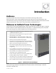
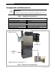


Table of Contents
2 900-0144-01-01 Rev B
List of Tables
Table 1 Components and Accessories ....................................................................................................... 4
Table 2 Battery Bank Elements ..................................................................................................................... 8
Table 3 Ground Conductor Size and Torque Requirements ........................................................... 19
Table 4 DC Conductor Size and Torque Requirements ..................................................................... 21
Table 5 AS4777.3 Acceptance Settings ................................................................................................... 40
Table 6 Terms and Definitions .................................................................................................................... 41
List of Figures
Figure 1 Radian Series Inverter/Charger .................................................................................................... 3
Figure 2 Radian Inverter and Components ............................................................................................... 4
Figure 3 Applications (Example) ................................................................................................................... 5
Figure 4 Bypass Switching ............................................................................................................................. 10
Figure 5 Bypass Switching for Multiple Inverters ................................................................................. 10
Figure 6 Inverter Dimensions ....................................................................................................................... 11
Figure 7 System Dimensions ........................................................................................................................ 12
Figure 8 Installing the Mounting Plate ..................................................................................................... 13
Figure 9 Mounting the Inverter ................................................................................................................... 14
Figure 10 Mounting for System Components .......................................................................................... 15
Figure 11 Removing the Front Cover .......................................................................................................... 16
Figure 12 DC Terminals, Ribbon Cables, and Auxiliary Terminals .................................................... 17
Figure 13 AC Terminals, Ports, and Ground Bus ...................................................................................... 18
Figure 14 Chassis Ground TBB ........................................................................................................................ 19
Figure 15 GS7048E and GS3548E Battery Terminals .............................................................................. 20
Figure 16 DC Cable Hardware (Radian inverter) ...................................................................................... 21
Figure 17 AC Terminals ..................................................................................................................................... 22
Figure 18 AC Sources ......................................................................................................................................... 23
Figure 19 Accessory Connections ................................................................................................................. 24
Figure 20 ON/OFF Jumper and Connections ............................................................................................ 24
Figure 21 AUX Connections for Vent Fan (Example) ............................................................................. 25
Figure 22 AUX Connections for Diversion (Example) ............................................................................ 26
Figure 23 Two-Wire Generator Start (RELAY AUX) ................................................................................. 27
Figure 24 Two-Wire Generator Start (12V AUX) ....................................................................................... 27
Figure 25 Three-Wire Generator Start (Example) .................................................................................... 28
Figure 26 Single-Inverter AC System ........................................................................................................... 29
Figure 27 Single-Inverter AC Wiring with GS Load Center .................................................................. 30
Figure 28 OutBack Communications Manager and System Display ............................................... 31
Figure 29 Example of Parallel Stacking Arrangement (Three Inverters) ........................................ 33
Figure 30 Parallel AC System .......................................................................................................................... 34
Figure 31 Parallel AC Wiring with GS Load Centers ............................................................................... 35
Figure 32 Example of Three-Phase Stacking (Three Inverters) .......................................................... 36
Figure 33 Example of Three-Phase Stacking (Nine Inverters) ............................................................ 36
Figure 34 Three-Phase AC System ................................................................................................................ 38
Figure 35 Three-Phase AC Wiring with GS Load Centers ..................................................................... 39