
Outback FX-R Series Installation Manual


Installation
24
900-0166-01-01 Rev A
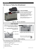
AC Sources
The inverter has a single set of AC terminals which are intended to connect to a single AC source.
It cannot be directly wired to more than one AC source at the same time.
If multiple sources are used, it is usually required to have a selector switch that changes from one
to the next. The switch should be the “break before make” type which disconnects from one source
before contacting another. This prevents the risk of connecting to two out-of-phase sources at the
same time or connecting them to each other.
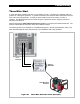
Figure 13 AC Sources
The inverter’s transfer relay is normally set to provide inverter power to the output. This is shown in
Figure 13, where the internal transfer relay is switched to the inverter function.
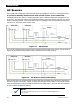
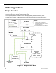
Figure 14 AC Sources and Transfer Relay
When an AC source is connected and accepted, the internal transfer relay switches to transfer the
AC source power to the loads. Figure 14 shows the utility grid switch closed. The internal transfer
relay has switched accordingly so that the loads receive utility power. (See the
Operator’s Manual
for the inverter’s acceptance criteria.)
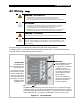
NOTE
:
The use of a GFCI-equipped AC source to power either the
G
RID
or
G
EN
input is not
recommended.
Utility Grid Generato
r
GND NEU HOT
NEU HOT (internal connections)
Inverte
r
OUTPUT
NEU
GND
Loads
Single-Pole
Double-
Throw
Switch
Internal
Transfer Relay
GND NEU HOT
Utility Grid
Generato
r
GND NEU HOT GND NEU HOT
Single-Pole
Double-
Throw
Switch
NEU HOT (internal connections)
Inverte
r
OUTPUT
NEU
GND
Load
Internal
Transfer Relay