
Outback FX-R Series Installation Manual


Installation
26
900-0166-01-01 Rev A
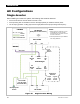
Accessory Wiring
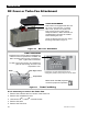
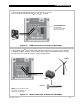
Figure 16 Accessory Connections
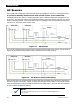
AUX Wiring
The AUX+ and AUX– terminals are a switched 12 Vdc supply. The AUX can respond to different
criteria and control many functions. These include cooling fans, vent fans, load diversion, fault
alarms, and the Advanced Generator Start (AGS) function.
The terminals can supply up to 0.7 amps at 12 Vdc (8.4 watts). This is sufficient to drive a small
fan or a relay controlling a larger device. The terminals accept wire up to #14 AWG (2.5 mm²).
The
A
UX
circuit contains electronic overcurrent protection, which resets after being overloaded.
No additional fuses are required for the
A
UX
terminals.
The default setting for the A
UX output is to control the Turbo Fan included with sealed models.
(See Figure 17.) The A
UX output can only control one function at a time. It cannot be used for
anything else if the Turbo Fan is connected.
The control logic for the
A
UX
output may be located in the inverter or it may be in the system display
or another location. FXR
A
UX
functions are located in the inverter and are described accordingly.
Although inverter-based functions require the system display for programming, they will function
even if it is removed. However, AGS programming is located within the system display even though
it uses the FXR
A
UX
terminals. It will not work if the display is removed. (Other devices may also
be able to control the terminals.) For generator control, see page 28.
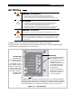
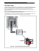
System Display cable
(RJ45, 8-conductor, CAT5
non-crossover)
MATE/HUB port
RTS port
The AC Wiring Compartment Board has ports
for both the Remote Temperature Sensor
(RTS) and the system display. The system
display port is labeled
M
ATE
/H
UB
.
See the Operator’s
Manual for more
information on
the RTS.
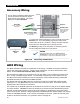
If a HUB Communications Manager is used, it occupies the inverter’s
M
ATE
/H
UB
port. The system display plugs into the HUB product.
Inverters plug into ports 1 and above. Charge controllers and other
devices plug into unassigned ports not used by inverters.
See
Stacking
on page 31 for information on connecting inverters.
See the HUB product literature for other devices.
NOTE
:
When first installing cables on the
B
ATTERY
T
EMP
and
M
ATE
/HUB
ports, make certain to apply silicone grease to
the connections. A packet is provided with the inverter.
MATE
p
ort
Additional
ports
RTS cable
(RJ11, 4-conductor,
telephone)