
Outback FX-R Series Installation Manual

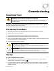

Commissioning
900-0166-01-01 Rev A
41
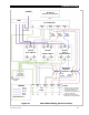
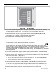
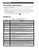
Figure 31 Three-Phase Wiring (Three Inverters)
CAT5 Cables
AC Source
(Utility Grid or AC Generator)
AC Conduit Box
Neutral
TBB
GND
Phase A
TBB
MATE3s
Inverter
AC
Neutral
IN
AC
Hot IN
(A)
HUB/
MATE
AC
Neutral
OUT
AC
Hot OUT
(A)
GND
Output
Circuit
Breakers
Bypass
Circuit
Breakers
Mechanical
Interlock
Neutral
TBB
GND
Phase A
TBB
AC
Loads
Ground TBB
(may be within
AC Conduit Box)
Primary System
Ground
LEGEND
Ground
Phase B
Neutral
TBB = Terminal Bus Bar
Phase B
TBB
Input
Circuit
Breaker
AC
Neutral
IN
AC
Hot IN
(B)
HUB/
MATE
Phase A Master
Phase B
Subphase Master
Inverter
AC
Neutral
OUT
AC
Hot OUT
(B)
GND
Phase B
TBB
Phase C
Phase C
TBB
AC
Neutral
IN
AC
Hot IN
(C)
HUB/
MATE
Phase C
Subphase Master
Inverte
r
AC
Neutral
OUT
AC
Hot OUT
(C)
GND
Input
Circuit
Breaker
Input
Circuit
Breaker
Phase
A
Phase C
TBB
HUB
10 9 8 7 6 5 4 3 2 1 MATE
NOTES:
1. Neutral (common) conductor
may be connected from only
one neutral terminal (per
inverter) to a common bus bar
in the AC conduit box.
2. Colors shown here may be
different from wiring standards.