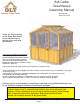
8x8 Cedar Greenhouse Assembly Manual Revision #9 April 27th, 2015 Thank you for purchasing an 8x8 Cedar Greenhouse. Please take the time to identify all the parts prior to assembly. Safety Points and Other Considerations Our products are built for use based on proper installation and normal residential use, on level ground. Please follow the instruction manual when building your Greenhouse and retain the manual for future maintenance purposes.
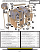
Thank you for purchasing our 8x8 Cedar Greenhouse. Please take the time to identify all the parts prior to assembly. KK Z X JJ G O M Rear EE Q P L V - Inside Vent Frame CC - Front Vertical Door Filler CCC- Front Hor. Door Filler Not Shown. I LL Y N C U OO BB H S K T W J E AA NN DD D Parts list F HH II GG FF R B A A - 4x4 - 44.25”...Foundation Posts - Front and Rear ..................x 4 pcs. B - 4x4 - 47 3/4”........Foundation Post s - Sides ...........................x 4 pcs.
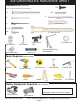
8x8 GREENHOUSE HARDWARE SHEET Hardware Kit (Provided) 3/4” Note: screws and nails shown actual size.
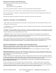
Selecting a Location for Your Greenhouse Walk around your property and make notes of the following: sunny spots slope of the land light blocking trees and high buildings. Don’t hide your greenhouse away in a dark corner of the garden. Make it an attractive feature. Ensure it has easy access to it and around it, to enable essential glass cleaning and general maintenance. Place the Greenhouse on a level piece of land with good drainage.
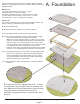
We recommend using a Sand & Gravel Foundation and Floor System because it is simple and cost ef fective to complete. Basic instructions are highlighted below. A. Foundation Material List: One Cubic Yard of Sand- to cover 9’x13’ - 2” deep. Landscape Clothe- to cover 8’x8’ footprint. 4x4 Cedar Foundation Framing - Included in Kit (Part s A & B). 1.5 Cubic Yards of Gravel (small) - to cover 8’x12’ - 4” deep. 4 Tie Down Kits or 12 pcs -12” long Rebar - Optional. 1.5 C ubic Yard s F.
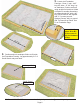
2. 1 /2 ” Locate 4x4 Foundation Framings. 2 front / 2 rear - 44.5” long & 4 sides - 47 3/4” long. Lay on sand base. Position and level using straight 2x4 and level. Make a footprint so outside dimensions are approximately 96” wide x 96” long. Screw ends of 4x4 together with 2- 3” screws per end. Optional- Secure 4x4’s to ground with Tie Down Kit or Rebar. See D. on Foundation Page. 95 3” screws 44 47 3/4 ” You can find the Square Drive Bit for the screws in with the Hardware Kit Bag.
4. Locate 4 pieces - Part C (3 1/2” x 3 1/2”x 76” ). Starting with front left corner, choose and orientate Post as shown to the left with short angle cut top to the outside and dado cuts running top to bottom to the inside. Posts attached filler trim will be orientated to the outside. Wall siding flush with post trim Important: Do not attach Walls to Foundation Framing until Step 19. 5.
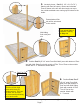
7. Complete remaining Corner Post/Wall attachments following Steps 4-6. 8. 2x4 facing up 2x3 facing down. Part R - Side Vertical Posts To complete remaining Post and Side W all attachments, locate 3 Side Vertical Posts (Part R) and 2 - 20 1/4” Wide Side W alls (Part E or F’s). On solid, level ground such as a p atio or deck lay the pieces down as shown below. You will need at least a 10’x10’ area. Place Side Vertical Posts with their 2x3’s face down.
Temporary Post/ Wall Supports (3” high x 2.5” wide) Important: Use a wood clamp to temporarily hold Post to Wall Framing. 2x4 Flush 9. Position Post R against Wall Framing as shown above. Make sure Post is flush with bottom of wall framing. Locate Temporary Post/Wall Supports (3” high) and place underneath 2x4 edge and touching 2x3 as shown above. Clamp and att ach Post to wall framing with 3 - 3” screws. Do both sides. Temporary Post/ Wall Support. 10. Complete 2nd Side Wall as per Step 8 & 9. 11.
12. Complete opposite Side Wall attachments as per Steps 9-11. Wall tight against Post. Use Clamp. Vertical Posts from Part I Set. 13. Locate Part I. The Doorway / Wall Framing Sets. There are 2 Sets (Front/Rear). Align and install Vertical Posts from the set as per Step 9. Install rear side first. 14. Install Part G. (Wide Rear Center Wall - 35” wide) as per Step 9. Toll Free 1-888-658-1658 www .outdoorlivingtoday.com Page 10 sales@outdoorlivingtoday.
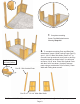
15. Install the Vertical Posts from the Front Set of Part G. as per Step 14. Part S Side Top Support 1 Cleat on end. 2 - 2” Screws. Bevel Cut 16. Cleats on both ends of Support. Locate Part S - Side Top Supports with a Bevel Edge. There are 2 pieces per side. Starting with Support with only one Cleat on the end, position on top of Side Wall Posts. Align Cleat end tight against Corner Post and attach with with 2 - 2” screws as shown above.
18. Repeat Steps 16-17 to complete opposite Side Top Support pieces. 19. 96" Measuring from the outside of Corner Post 4x4’s, 4 ft up, your Greenhouse should have a footprint ideally of 96” wide x 95 1/2” deep. There can be small tolerances when connecting post/walls together resulting in a variation on the depth of approx. 1/2”. 95 1/2" If using Wood Foundation Posts supplied, screw walls down onto foundation with 2 - 3” screws per panels. Doorway Opening = 32” from 2x4’s.
21. Repeat Step 20 to attach Left Side Front Wall Top Cap. Left Side 21. Locate Part T - Side Wall Top Caps - 1 1/2” x 5 1/2” x 44 1/8”. Position and attach as per Step 20. The Cap is designed with tolerance and gap s will appear around the notches. Later, caulking may be applied to seal these gap s. 22. Complete Side Wall Top Cap on one side. Depending on your footprint measurement, a gap of 1/8” to 1/2” could result where Caps meet in the middle. You may use caulking later to seal the gap.
Rear Wall Top Caps 23. Locate Part H - Rear Wall Top Caps 1 1/2” x 5 1/2” x 44 1/2”. Position and attach as per Step 20. Once again, the Cap is designed with tolerance and gaps will appear around the notches. Later, caulking may be applied to seal these gap s. Complete remaining Side Wall Top Cap attachments as shown to the left. Important: Outside Angle Cut Polygal Window Install Polygal Windows in sequence outlined in this manual. position in gap. position in dado cut. 24.
25. Slide Window down into the dado cut of the Top Cap. 26. Locate Part L - Rear Center Polygal Window 33 3/4” wide. Once again, peel protective plastic layer of f first and note correct side out. On a step ladder , lift window up and position between gap of Doorway Posts. Slide down and position as per Step 25. 27. Locate a second Part K - Outside Angle Cut Polygal Window - 26 1/2” wide. Position as per Step 24-25. Toll Free 1-888-658-1658 28.
29. Make sure the Window Slides down into the dado cut of the Top Cap. Position remaining corner Polygal windows as shown to the right. (3 outside Side Windows and 2 front Angle Cut Windows.) Cap’s 2x4 has angle cut ends at top. 30. Position,attach and complete Horizontal Top Cap from Doorway/ Wall Framing Set Part I - 30” long. Cap will sit on Doorway Framing. Use 4 - 3” screws to secure. Attach from the inside. Complete both front and rear Cap s. Toll Free 1-888-658-1658 www .outdoorlivingtoday.
Part O King Stud. Part Q Gable Support Frame. Mark Centers 31. Locate Parts O & Q - King Stud and Gable Support Frame. Using a tape measure, mark centers on bottoms of Horizont al Top Cap / King Stud / Gable Support Frame. Center Gable Support on Cap and t ack together only with 2 - 2” screws. Center King S tud on Support Frame and tack also with 1 - 3” screws. Complete both front and back pieces. In Step 42., some adjustment may be required. Completely att ach then. Tack in screws to hold in position.
6” Lag Screws with Washer. Flush 33. Position Rafter so end is flush with Corner Post and Out side Polygal Angle Cut Window slides into dado cut of Rafter. When orientated correctly, start 2 - 6” Lag Screws with 3/8” W asher with a hammer and tighten with 9/16” socket. 34. Locate Part M - Top Triangular Polygal Windows. Slide Window in Top Cap gap and into dado cut of Rafter. 35. Locate Left Side Rafter and orientate as shown above.
36. Carefully Slide Rafter up until end of Rafter is flush with Post as shown above. Make sure Angle Cut Window and Triangular Window stays in dado cut of Rafter. 37. When Rafter is orientated correctly, start 2 - 6” Lag Screws with W ashers with a hammer and tighten with 9/16” socket. From the inside, att ach Gable Support Frame to Rafters with 4 - 1 1/4” screws. See illustration below . Rear Wall shown with Rafters, King Stud and Gable Support Frame configured correctly.
38. Complete Front Outside Roof Rafters and Triangular Polygal Window as per Steps 32 -37. Flush 39. Attach Part OO - Exterior Rafter / Doorway Supports - 1 1/2” x 1 1/2” x 27 1/2” underneath and flush with Outside Rafters. Use 3 - 3” screws per piece to secure. Complete front and rear pieces. dado cuts aligned 40. Locate Part P - Roof Ridge Boards - 2” x 5 1/2” x 59 1/4”. There are 2 pieces that need to be fastened together. Aligning dado cuts and attach with 6 - 2” screws per side.
High Side 41. Before installing completed Ridge Board, note that dado cut is of f center. Orientate Ridge Board with high side to top before lifting. See illustration above. Dado cuts line up Notch Make sure Support does not block Roof Window from sliding up dado cut. Flush angle 3” screw King Stud/ Support may need to be re-positioned. 42. Drop Ridge Board into King Stud notch. Dado cut of Ridge Board should line up with dado cut of Rafters.
44. Once all Side Windows are installed. Caulk Window / Wall Top Cap seam. Work around the entire Greenhouse. Gaps in Wall Top Caps can also be caulked at this time. No need to caulk sides or top at this time. Spacer tight against Outside Rafter Rafter Template Spacer - 20 3/16”. Spacer tight against 2x3. Align dado cuts with gap in Rafter. 45. Locate Part U - Roof Rafters - 3 1/4” x 3 1/2” x 50 3/4” and Rafter Template Spacer - 20 3/16”.
46. Install second Part U - Roof Rafter using Rafter Template Spacer. Align Spacer tight against Rafter’s 2x3 edge. Position Rafter so dado cut of Ridge Board is aligned with gap in Raf ter and tight against 2x3 edge of new Rafter. Attach as per Step 45. 47. Install Rafters as illustrated above and to the right as per Steps 45 & 46. Part V - Inside Vent Framing Support Part V - Inside Vent Framing Support 48. Confirm Rafter locations using Part V (Inside Vent Framing Support) .
49. Standing on a ladder from the inside, position and attach Part Z - Vent Hinged Window to Ridge Board. Middle Rafter 50. Prior to attaching, confirm Window can move up and down freely and is centered evenly on Rafters. When satisfied with location, attach Vent Hinged Window to Ridge Board with 3 - 3/4” black screws per hinge. 51. Locate Part X - Roof Polygal Windows 21 ” wide x 51” long. Peel protective plastic layer off first sheet noting correct side out.
Dado cut of Ridge Board 52. Slide Roof Window up dado cut and gap of Raf ters until it slides completely into dado cut of Ridge Board. 1 1/2” finishing nails Caulk seam 53. With Window in position, use 2 - 1 1/2” finishing nails to secure. Window should be slightly recessed or flush from end of Raf ter and back approximately 1/4” from end of Out side Rafter. Standing on ladder from inside the Greenhouse, caulk the Ridge Board / Window Seam. 54.
Even with end of Ridge Board. 55. Before installing remaining Roof Windows, attach Part KK - Top Ridge Caps - 1” x 5 1/2” x 47 5/8” to top of Ridge Board. On a ladder , position 1 Cap evenly on Ridge Board and flush with the out side. Attach with 3 - 3” screws as illustrated above. Attach 2nd Cap. Work from the inside on a step ladder to att ach. 56. Install remaining Roof Polygal Windows as per Steps 51-53. Toll Free 1-888-658-1658 www .outdoorlivingtoday.com Page 26 sales@out doorlivingtoday.
Inside Vent Framing Support 57. Locate and attach Part V - Inside Vent Framing Support - 3/4” x 2 1/2” x 49” with 6 - 2” screws. Position parallel with Hinged Window. Marked Lift Window Open 58. Locate Heat Activated Hinge. Heat Activated Hinge will require a basic assembly. Follow Manufacturer’s directions. Attach with Manufacturer’s Hardware supplied. Phillips Head Driver will be required. To install, open Window from the inside. Hinged Window will be marked for correct location for Hinge.
59. Locate Part Y - Small Roof Polygal Windows - 21” wide x 24 1/2” long. Peel protective plastic layer off noting correct side out. Fit Window in Raf ter gaps and attach as per Step 53. Caulking not required. Complete all Small Roof Windows. 60. Locate Part CC & CCC - Vertical and Horizontal Door Filler Trim - 3/4” x 2 1/2” x 33” & 87 1/4” long. Position 3/4” Vertical Filler Trim on Doorway Framing and attach with 6 - 1 1/2” finishing nails. There are two pieces. Toll Free 1-888-658-1658 www .
61. Position 3/4” Thick Horizontal Filler Trim above Doorway and attach with 4 - 1 1/2” finishing nails. 62. Locate Part DD & EE - Vertical & Horizontal and Vertical Door Trim - 1/2” x 2 1/2” x 38” & 84 1/4”. Position 1/2” Thick Horizontal Trim over Horizontal Filler Trim and attach with 4 - 1 1/2” finishing nails. Position 1/2” Thick Vertical Trims over Filler Trims and attach with 6 - 1 1/2” finishing nails per piece. Butt Hinge Align Door and Wall Caps. 63.
1/4” Gap 64. Locate Part BB - Top Dutch Door - 32 1/2” x 47”, 2 - Black Butt Hinges and 12 - 2” Black Screws. On ground, attach Hinges to Door first using 2” Black Screws. Align/shim 1/4” from Bottom Door and attach to Door Trim with 2” Black Screws. Confirm Door swings correctly before attaching all screws. 65. Attach Door Handle and Exterior Black Barrel Bolt to door. Handle is positioned on top door; Barrel Bolt on bottom door.
Narrow Wide 67. Locate Parts FF & GG - Outside Post Trim Narrow- 1/2” x 4 1/2” x 34 7/8” and Outside Post Trim Wide - 1/2” x 5 1/2” x 34 7/8”. Position with Wide Trim capping the side when looking at the front. Align Trims so flush under Wall Top Caps and attach with 4 - 1 1/4” finishing nails per piece. 68. Complete remaining Outside Post Narrow and Wide Trims. 69. Locate Part HH -Vertical Wall Trim - 1/2” x 3 1/2” x 34 7/8”. Position underneath Top Wall Cap where Walls attach to Posts.
70. Locate Part II - Corner Post Trim - 1 1/2” x 1 1/2” x 5”. Position around each Outside Corner Post. Attach with 2 - 2” finishing nails per piece. 19 1/2” long 71. Locate Part LL - Side Soffits - 1/2” x 4” x 19 1/2”(4) & 19 1/8”(4). Position underneath Roof Window and between Outside and Side Post. Orientate Soffit with rough face out and lap siding down and to the inside to cap Side Window . Attach with 4 - 1 1/2” nails. Finish all corner Sof fits now. 72.
73. Locate Part JJ - Detail Caps - 1/2” x 3 1/2” x 10”. Position to cover Post and Rafter connection. Attach with 4 - 2” finishing nails per piece. In the Front and Rear, attach Cap to cover Rafter/Ridge Board connection. Attach with 4 - 1 1/2” finishing nails. 74. Locate Parts MM and NN - Potting Shelves - 16” x 43 3/4” and Potting Shelf Supports 1 1/2” x 2 1/2” x 20 1/2”. With helper holding Shelf just under the Top Wall Cap, screw to wall from underneath with 3 - 3” screws as shown above. 75.
76. Complete all Shelving and Supports! Note; Our Greenhouse is shipped as an unfinished product. If exposed to the element s, the western red cedar lumber will weather to a silvery-gray color. If you prefer to keep the cedar lumber looking closer to the original color, we suggest that you treat the wood with a good oil base wood st ain. You may also wish to paint rather than stain. In both cases we recommend that you consult with a paint and stain dealer in your area for their recommendations.