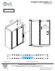
SYDNEY SIDE PANEL 32 ITEM #667449 Measures: millimeter [inch] 24 15 ] / 60 19 12 8] / [ [4 81 [32 3 ] Opening 485 / 615 [19 3/32] / [24 7/32] 2000 [78 3/4] 2000 [78 3/4] 180 [7 3/32] CSA Markings An installation video guide can be found on our Youtube channel. http://youtu.
SAFETY INFORMATION CAUTION Please carefully read the following important safety information before handling or installing this shower. There is a risk of serious injury while handling this product. To minimize these risks, please note: • Always wear safety glasses and gloves while handling. • Always read and follow all the steps in the installation instructions. • Inspect all contents and glass for damage before installation.
TABLE OF CONTENT PACKAGE CONTENT.......................................................................................................................................... 5 HARDWARE CONTENT...................................................................................................................................... 6 TOOLS REQUIRED............................................................................................................................................. 6 SHOWER REVERSIBILITY........
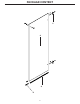
PACKAGE CONTENT P O Q R 4
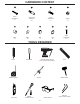
PACKAGE CONTENT PART# DESCRIPTION QTY CODE O Side panel 1 99SG10034-WM P Side panel fixture 2 99SGC1047-WM Q Side panel’s bottom seal strip 1 99SRU0115 R Side panel’s clamp 1 99SGC1048-WM 5
HARDWARE CONTENT DD FF OO PP Screw ST5x40mm 2+1 Wall Anchor ø8x30mm 2+1 Screw ST8x30mm 1x Fitting 1x RR QQ SS TT UU Fitting 1x Fitting 2x Cap 1x Cap 4x Screw ST5x25mm 2+1 TOOLS REQUIRED Pencil Screwdriver Measuring Tape Box cutter Drill with ceramic tile bits 3mm (1/8 in) & 8mm (5/16 in) Silicone Ratchet 5 mm Bit socket Rubber mallet Safety glasses 6 Level Allen key 2.
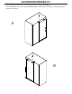
SHOWER REVERSIBILITY • This instruction is drawn up for an opening from right to left (see illustration A). • For an installation from left to right (see illustration B), use the same instructions, but switch around the panels: mirror effect.
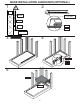
1 BASE INSTALLATION GUIDELINES (OPTIONAL) 2 Studs Tile Wall Shower Base Drywall Cement Flange Silicone Floor Shower Base 3 4 Wood shim Flange Stud 5 Drywall Silicone 8
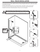
WALL TRACK INSTALLATION 1. Ensure the base and walls are leveled. Place the metal track (B) approximately 20mm (3/4in) from the edge of the base to the center of the metal track. Ensure the metal track (B) is leveled, then mark the holes clearly on the wall using a pencil. 2. Remove track and drill pilot holes in the marked locations. Using Φ8mm (5/16in) ceramic drill bit. 3. Insert the wall anchors (EE) using a rubber mallet until the wall anchors are flush with the wall. 4.
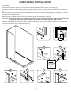
FIXED PANEL INSTALLATION 1. Insert the fixed panel’s bottom seal strip (I) at the base of the fixed glass panel (A), 40mm (1 9/16in) from the panel’s edge. 2. Place the sliding door guide (E) on the base. Ensure the distance that is shown in the image (2). 3. Mark the positions of holes of the sliding door guide (E) with a pencil, and drill pilot holes with a ø3mm (1/8in) drill bit. 4. Fix the sliding door guide (E) with the screw (BB) and cap (KK).
SIDE PANEL INSTALLATION 1. Place side panel’s vertical seal strip (Q) to the side panel (O). 2. Place the side panel onto the clamp (R). 3. Install the support bar’s anchors (N), support bar (D) and the stoppers (M) together. 4. Install the support bar to the side panel (O), using screw (OO), fitting (PP & QQ & RR) and cap (SS). 5. Install the fixer (P) to the side panel (O), using screws (DD). 6-7. Mark the positions of the fixer (P) and the clamp (R). 8-9. Remove the fixer (P) and the clamp (R). 10.
SIDE PANEL INSTALLATION 1. Drill pilot holes with a ø3mm (1/8in) drill bit. 2. Secure the clamp (R) onto the base with screws (UU). Ensure the plastic gasket in the guide is in place as it protects the side panel. 3-4. Drill pilot holes in the marked locations of the fixer with a Φ8mm (5/16in) drill bit. Insert the wall anthor (EE). 5-6. Install the side panel (O) and the support bar. 7-8. Scure the fixer (P) to the wall anthor (EE) with screw (DD) and the cap (TT).
DOOR INSTALLATION 1. Install the 2 top rollers (K) on the door glass panel (C). Use a ratchet to strongly tighten the blots. 2. Insert the door bottom seal strip (L) onto the door panel (C). 3-4. Gently hang the door panel by its 2 top rollers on the support bar (D) and make sure to place the bottom of the door inside the guide (E). 5. Install the 2 bottom rollers (K) on the door glass panel (C) 6-7. Install the 2 glass panels seal strips (F). 8.
HANDLE INSTALLATION & SEALING 1. Install the door handle (H) using Allen keys (MM). 2. Ensure that the door closes tightly and opens smoothly, and that there is a tight connection between the side glass panels and the frame as well as the support bar. Apply a clear silicone water sealant around the outside perimeter of any fixed shower components (horizontally between bottom of fixed side glass panel and base, as well as vertically between the wall, glass frames, and any side glass panel).
OVE Decors ULC LIMITED Product Warranty OVE is a distributor of the following Products: • Shower Doors (warranty period 5 years). • Acrylic Surfaces (warranty period 5 years against blistering, cracking or chipping in the acrylic surface). • Acrylic Shell Structure (warranty period 5 years against loss of water through fiberglass laminate of the acrylic body).
SYDNEY PANNEAU LATÉRAL 32 ITEM #667449 Mesures: millimètres [pouces] 24 15 ] / 60 19 12 8] / [ [4 81 [32 3 ] Ouverture 485 / 615 [19 3/32] / [24 7/32] 2000 [78 3/4] 2000 [78 3/4] 180 [7 3/32] Marques CSA Un guide d’installation video est disponible sur notre chaîne Youtube. http://youtu.
INFORMATION SUR LA SÉCURITÉ AVERTISSEMENT Veuillez lire attentivement les importantes consignes de sécurité suivantes avant la manutention et l’installation de cette douche. La manipulation de ce produit présente un risque de blessure grave. Pour minimiser ces risques, veuillez prendre note de ce qui suit: • Toujours porter des lunettes et des gants de sécurité pendant la manutention. • Toujours lire et suivre toutes les étapes indiquées dans les instructions d’installation.
TABLE DES MATIÈRES CONTENU DE L’EMBALLAGE..........................................................................................................................20 QUINCAILLERIE FOURNIE.............................................................................................................................. 21 OUTILS REQUIS............................................................................................................................................... 21 CETTE DOUCHE EST RÉVERSIBLE........
CONTENU DE L’EMBALLAGE P O Q R 19
CONTENU DE L’EMBALLAGE # DE PIÈCE DESCRIPTION QUANTITÉ CODE O Panneau latéral 1 99SG10034-WM P Attache du panneau latéral 2 99SGC1047-WM Q Joint d’étanchéité pour panneau latéral 1 99SRU0115 R Serre-joint pour panneau latéral 1 99SGC1048-WM 20
QUINCAILLERIE FOURNIE DD FF OO PP Vis ST5x40mm 2+1 Ancrage mural ø8x30mm 2+1 Vis ST8x30mm 1x Raccords 1x RR QQ SS TT UU Raccords 1x Raccords 2x Capuchon 1x Capuchon 4x Vis ST5x25mm 2+1 OUTILS REQUIS Crayon Tournevis Ruban à mesurer Exacto Perceuse avec foret à ceramique 3mm (1/8 po) & 8mm (5/16 po) Silicone Clé à rochet Embout 5mm Maillet en caoutchouc Lunettes de sécurité 21 Niveau Clé Allen 2.
CETTE DOUCHE EST RÉVERSIBLE • Utilisez ces instructions pour une ouverture de la porte de droite à gauche (illustration A). • Pour une installation de gauche à droite (illustration B), suivez ces mêmes instructions mais permutez l’emplacement des panneaux: effet miroir.
GUIDE D’INSTALLATION DE LA BASE (OPTIONNEL) 1 2 Montant mural Mur de tuiles Base de douche Placoplâtre Ciment Bride Silicone Plancher Base de douche 3 4 Cale en bois Bride Montant mural 5 Placoplâtre Silicone 23
INSTALLATION DU RAIL MURAL 1. S’assurer que la base et les murs soient à niveau. Placez le rail mural (B) approximativement à 20mm (3/4”) du bord de la base jusqu’au centre du rail. S’assurer que le rail mural (B) soit à niveau, ensuite marquez les trous clairement sur le mur. 2. Retirez le rail et percez les trous guide aux endroits marqués avec un foret Φ8mm (5/16po). 3. Insérez les ancrages muraux (EE) en utilisant un maillet en caoutchouc. 4. Replacer le rail (B) et le fixer avec les vis (CC).
INSTALLATION DU PANNEAU FIXE 1. Insérez le joint d’étanchéité du panneau fixe (I) à la base du panneau (A), à 40mm (1 9/16po) du bord de la base. 2. Placez le guide (E) sur la base, et s’assurez de respecter les distances montrées à la figure (2). 3. Marquez la position des trous du guide avec un crayon et percez 2 trous guides avec un foret ø3mm (1/8po). 4. Fixez le guide de la porte coulissante (E) avec les vis (BB) et le capuchon (KK).
INSTALLATION DU PANNEAU LATÉRAL 1. Placez le joint d’étanchéité du panneau latéral (Q) au panneau latéral (O). 2. Placez le panneau latéral sur le serre-joint (R). 3. Installez l’ancrage de la barre de support (N), la barre de support (D) et la buttée (M) ensemble. 4. Installez la barre de support au panneau latéral (O) avec les vis et les raccords (PP&QQ&RR) et les capuchons (SS). 5. Installez l’attache(P) au panneau latéral (O) avec les vis (DD). 6-7.
INSTALLATION DU PANNEAU LATÉRAL 1. Percez trois trous avec un foret 3mm (1/8po). 2. Sécurisez le serre-joint (R) sur la base avec les vis (UU). Assurez-vous que le joint en plastique dans le guide est bien en place, car il protège le panneau latéral. 3-4. Percez les trous à l’endroit où vous les avez marqués sur l’attache avec un foret 8mm (1/4po). Insérez l’ancrage mural (EE). 5-6. Installez le panneau latéral (O) dans la barre de support. 7-8.
INSTALLATION DE LA PORTE 1. Installez les 2 roues du dessus (K) sur la porte (C). Utilisez une clé à rochet afin de serrer les boulons fortement. 2. Insérez le joint d’étanchéité (L) au bas de la porte (C). 3-4. Suspendre la porte sur la barre (D) par les 2 roues et placer le bas de la porte dans le guide (E). 5. Installez les 2 roues du bas (K) sur la porte (C) 6-7. Installer les 2 joints d’étanchéité verticaux (F). 8. Installez le rail décoratif (J) à l’avant de la porte en utilisant du silicone.
INSTALLATION DE LA POIGNÉE ET SCELLAGE 1. Installer la poignée (H) en utilisant une clé Allen (MM). 2. Assurez-vous que la porte se ferme hermétiquement et s’ouvre doucement, et que le châssis et la barre de support sont étroitement fixés aux panneaux de verre.
OVE Decors ULC Garantie LIMITÉE du produit OVE est distributeur des produits suivants: • Portes de douche (garantie de cinq ans). • Surfaces en acrylique (garantie de cinq ans contre le cloquage, le craquelage ou l’écaillage de la surface en acrylique). • Structure en acrylique de la coque (garantie de 5 ans contre les fuites d’eau à travers le stratifié en fibre de verre de la coque en acrylique).
SYDNEY PANEL LATERAL 32 ITEM #667449 Medidas: milímetros [pulgadas] 24 15 ] / 60 19 12 8] / [ [4 81 [32 3 ] Apertura 485 / 615 [19 3/32] / [24 7/32] 2000 [78 3/4] 2000 [78 3/4] 180 [7 3/32] Marca CSA Una guía de instalación de vídeo está disponible en nuestro canal de Youtube. http://youtu.
INFORMACIÓN DE SEGURIDAD PRECAUCIÓN Lea cuidadosamente la siguiente información importante antes de manipular e instalar la ducha. Hay riesgo de lesiones graves mientras se manipula el producto. Para minimizar estos riesgos, sírvase notar: • Utilice siempre anteojos de seguridad y guantes durante la manipulación. • Lea y siga siempre todos los pasos en las instrucciones de instalación. • Inspeccione todo el contenido y el vidrio por daños antes de la instalación.
TABLA DE CONTENIDOS CONTENIDO DEL PAQUETE............................................................................................................................ 35 CONTENIDO DE HARDWARE.......................................................................................................................... 36 HERRAMIENTAS NECESARIAS...................................................................................................................... 36 REVERSIBILIDAD DE LA DUCHA.........................
CONTENIDO DEL PAQUETE P O Q R 34
CONTENIDO DEL PAQUETE PARTE# DESCRIPCIÓN CANTIDAD CÓDIO O Panel lateral 1 99SG10034-WM P Pieza de fijación de panel lateral 2 99SGC1047-WM Q Tira de sellado inferior del panel lateral 1 99SRU0115 R Abrazadera del panel lateral 1 99SGC1048-WM 35
CONTENIDO DE HARDWARE DD FF OO PP Tornillo ST5x40mm 2+1 Tarugo ø8x30mm 2+1 Tornillo ST8x30mm 1x Accesorio 1x RR QQ SS TT UU Accesorio 1x Accesorio 2x Capuchón 1x Capuchón 4x Tornillo ST5x25mm 2+1 HERRAMIENTAS NECESARIAS Lápiz Destornillador Cinta medidora Cuchilla Taladro con brocas para cerámica 3mm (1/8pu) & 8mm (5/16pu) Silicona Llave de trinquete Copa de 5mm Mazo de goma Anteojos de seguridad 36 Nivel Llave Allen 2.
REVERSIBILIDAD DE LA DUCHA • Estas instrucciones fueron elaboradas para una abertura de puerta de derecha a izquierda (ilustración A). • Para una abertura de izquierda a derecha (ilustración B), siga estas mismas instrucciones, pero cambie el lugar para la ubicación del riel: efecto espejo.
PAUTAS PARA LA INSTALACIÓN BASE (OPCIONAL) 1 2 Soportes Pared de Baldosas Plato de ducha Tablaroca Cemento Brida Silicona Piso Plato de ducha 3 4 Madera cuñas Brida Soportes 5 Tablaroca Silicona 38
INSTALACIÓN DEL RIEL DE LA PARED 1. Asegúrese de que la base y las paredes estén niveladas. Coloque el riel metálico (B) a aproximadamente 20mm (3/4 pulg.) desde borde de la base hasta el centro del riel metálico. Asegúrese de que el riel metálico (B) esté nivelado, marque claramente el sitio para los agujeros en la pared utilizando un lápiz. 2. Retire los rieles y perfore los agujeros guía en los sitios marcados con una broca de Φ8mm (5/16pu). 3.
INSTALACIÓN DEL PANEL FIJO 1. Inserte la tira de sellado inferior (I) del panel fijo en la base del panel de vidrio fijo (A), a 40mm (1 9/16pu) del borde del panel. 2. Placez le guide (E) sur la base, et s’assurez de respecter les distances montrées à la figure (2). 3. Marquez la position des trous du guide avec un crayon et percez 2 trous guides avec un foret ø3mm (1/8pu). 4. Fije la guía de la puerta corrediza (E) con el tornillo (BB) y el capuchón (KK).
INSTALACIÓN DE LA BARRA DE SOPORTE 1. Coloque la tira de sellado vertical del panel lateral (Q) al panel lateral (O). 2. Coloque el panel lateral en la abrazadera (R). 3. Instale el anclaje de la barra de soporte (N), la barra de soporte (D) y los retenedores (M) juntos. 4. Instale la barra de soporte al panel lateral (O), utilizando el tornillo (OO), los accesorios (PP y QQ y RR) y el capuchón (SS). 5. Instale la pieza de fijación (P) al panel lateral (O), utilizando los tornillos (DD). 6-7.
INSTALACIÓN DE LA BARRA DE SOPORTE 1. Perfore los agujeros piloto con una broca de ø3mm (1/8 pu). 2. Fije la abrazadera (R) sobre la base con los tornillos (UU). Asegúrese de que de que la empaquetadura de plástico en la guía esté en su lugar ya que protege el panel lateral. 3-4. Perfore los agujeros piloto en los lugares marcados en la pieza de fijación con una broca de Φ8mm (5/16 pulg.). Inserte el tarugo de pared (EE). 5-6. Instale el panel lateral (O) en la barra de soporte. 7-8.
INSTALACIÓN DEL PANEL DE LA PUERTA 1. Installez les 2 roues du dessus (K) sur la porte (C). Utilisez une clé à rochet afin de serrer les boulons fortement. 2. Insérez le joint d’étanchéité (L) au bas de la porte (C). 3-4. Suspendre la porte sur la barre (D) par les 2 roues et placer le bas de la porte dans le guide (E). 5. Installez les 2 roues du bas (K) sur la porte (C) 6-7. Installer les 2 joints d’étanchéité verticaux (F). 8.
INSTALACIÓN DE LA MANIJA Y SELLADO 1. Instale la manija (H) de la puerta utilizando la llave Allen (MM). 2.
OVE Decors ULC Garantía LIMITADA de productos OVE es un distribuidor de los siguientes productos: • Puertas de ducha (periodo de garantía de 5 años). • Superficies acrílicas (periodo de garantía de 5 contra formación de burbujas, grietas o desportilladuras en la superficie de acrílico). • Estructura de cubierta de acrílico (periodo de garantía de 5 años contra la pérdida de agua a través del laminado de fibra de vidrio del cuerpo de acrílico).