
Owner's Manual
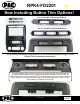
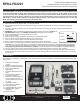
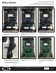
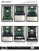
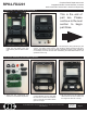
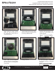
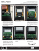
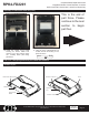
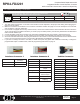
Table Of Contents

Complete Radio Replacement with
Integrated Climate Control Retention for select
2015-2018 Ford F150 and 2017-2018 Ford Super Duty
RPK4-FD2201
© 2019 AAMP Global. All rights reserved. PAC is a Power Brand of AAMP Global.
PAC-audio.com
Pacific Accessory Corporation
Page 9
Rev. V7
Date:020419
DIP Switches and Wiring Connections
3.5mm Jack SWC Output
Pink MS-CAN + Input
Pink / Black MS-CAN - Input
Blue / Yellow SWC Output
Red / White 12v+ Programmable
Output
Orange / White Illumination Output
Pink Vehicle Speed
Sense Output
Violet / White Reverse Output
Light Green Parking Brake
Output (-)
Interface Connector 2
Yellow Battery +12v
Black Ground
Pink MS-CAN +
Pink / Black MS-CAN -
Blue / White Not Used
Brown Center CH - Input
Brown / White Center CH + Input
White Front L + input
White / Black Front L - input
Grey Front R + input
Grey / Black Front R - input
Green Rear L + input
Green / Black Rear L - input
Purple Rear R + input
Purple / Black Rear R - input
Vehicle Connector
Interface Connector 1
Red Accessory Output
(10 amps)
Yellow 12v+
Black Ground
1. The radio select DIP switches on the side of the interface must be adjusted to the proper radio setting before plugging the
interface into the vehicle.
2. Make all connections as described in the connection chart below. Please see page 12 for a full description of the functions
and connectivity of the red / white wire.
3. If the vehicle is equipped with a factory reverse camera, connect the included reverse camera retention harness to either the
12-pin or 54-pin plug found behind the factory 4” monitor (only one will be present). Connect the yellow RCA to the aftermarket
radio’s reverse camera input.
4. Connect the SWC output wire according to the chart below (aftermarket radio must support a wired remote input).
5. If you are adding blind spot and / or front cameras, wire up the VS41 (sold separately) as outlined on the next page.
6. Once all connections have been made, plug the interface into the vehicle. It is recommended that this be done with the vehicle
running. Once the interface has been connected the LED will blink until initilization is complete.
7. If you wish to reassign functions to the SWC, or utilize short press long press dual command functionality, or assign the
programmable output to a SWC button, follow the programming instructions on page 11.
DIP
1 2 3 4
ON
Alpine JVC Kenwood Clarion Pioneer/Other Sony Fusion
1 2 1 & 2 3 1, 2, & 3 4 1 & 4
Other = Advent, BOYO, Dual, Lightning Audio, Rockford Fosgate, Visteon
Set DIP switches that match your radio to the ON position
Set all other DIP switches to the OFF position