AeGIS NPB9000 Series Installation and Programming Manual REV. 08.31.10 PACH & COMPANY www.pach-co.
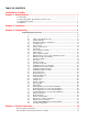
TABLE OF CONTENTS Limitations of Liability Chapter 1. Getting Started ............................................................................................. 1 1.1. 1.2. 1.3 1.4 Introduction .................................................................................................................................. 1 System Description, Specifications and Accessories .................................................................. 1 Unpacking the System ........................................
How to Extend the Talk Time ............................................................................................................. How to use the Call Waiting .............................................................................................................. How to Use the Doorman or Manager Phone .................................................................................. How to use the Keypad Access Code...............................................................................
LIMITATIONS OF LIABILITY This manual is subject to change without notice. Pach and Company is not liable for any errors that might occur from use of this document, nor is any commitment to update the information herein implied. Pach and Company does not assume any liability for any damages, which may arise in installation or use of the AeGIS NPB9000 Series. Pach and Company does not assume liability for any incompatibility between the AeGIS NPB9000 Series and users devices.
Chapter 1 GETTING STARTED 1.1 Introduction Pach & Company thanks and congratulates you on the purchase of your AeGIS NPB9000 Series Telephone Access Control Systems with optional 26 Bit Wiegand Proximity Reader or Radio Reader with remote or local programming via software. The manual is designed to guide you through the proper programming and use of the AeGIS NPB9000 Series. It is important for you to read and follow the manual completely.
Technical Specifications: AeGIS NPB9000 Series Power Input: 12 VAC 40 VA (supplied) or 12 VDC 40VA UL Listed Transformer Current Consumption: AeGIS 9000NCMain Lobby Control Panel: Min 700mA idle, Max 900mA operation with optional Wiegand Card Reader and Radio Reader. MS79xxx Main Relay Control Panel: 50 mA Idle, 680 mA Operation. MX79xxx Expanded Relay Panel: 50 mA Idle, 680 mA Operation. Emergency Battery: 12Vdc, 4Ahr rechargeable (not supplied) Telephone Line: Standard voice grade RJ11 jack.
• Warranty Card with unit serial number. 1.4 Limited Warranty Pach and Company new products are warranted to be free of defects in material or workmanship for a period of two years, (24 months), from the date of purchase. This warranty extends only to wholesale customers who buy direct from Pach and Company or through Pach and Company’s normal distribution channels. Pach and Company does not warrant this product in any way to the end user consumer.
NEW PRODUCT WARRANTY EXCEPTION WIEGAND CARD, KEYFOB AND TRANSMITTER Pach and Company warrants the wiegand card, clam, and keyfob to be free of defects in material or workmanship for a period of three (3) months from the date of invoice. The above warranty is subject to the following conditions. 1. The products must be properly installed as specified; and maintained or used as intended. 2.
written authorization from Pach and Company Technical Department, with such authorization given only to manufacturer approved dealer/installers. 4. Under no circumstances will Pach and Company honor warranty any product found to have been altered, repaired, and/or modified by the end-user consumer. 5. Pach and Company reserves the right to replace a warranted product with a like product of equal value in the event original system cannot be repaired. 6.
7. Return Merchandise Authorization (RMA) numbers will not be issued to the end-user consumers. Consumers must contact their selling dealer-installer for any/all warranty issues. 8. Distributor and/or Dealer-Installer are responsible for all shipping charges, incl. freight and insurance fees, for products shipped to Pach and Company repair center. 9.
Chapter 2 INSTALLATION 2.1 System’s Wiring A proper installation of the AeGIS system is very essential. You MUST follow the installation procedures, block diagrams and installation requirements as specified in this chapter. Optional 26 Bit Wiegand Card 9 Reader or Wiegand RED Radio Reader BLACK Input. We will not resposible WHITE for incompatibility GREEN issue if using other than Pach & Co 10 Proximity Reader.
2 1 14 11 EXPANSION RELAY PANEL MX79012 - MX79120 12 1 MAIN RELAY CONTROL PANEL MS79012 - MS79120 Figure 2.
15 15 RJ71X24 RJ71X12 Figure 2.3a 1 Figure 2.3b GROUNDING Grounding the AeGIS 9000NC, MS79xxx and MX79xxx steel enclosure are essential. Please comply with all local ordinances and industry standard procedures to ensure a complete and safe ground. Recommended earth grounds are: • • • • • Use 18-gauge solid wire for grounding. Installing a ground steel rod from the steel enclosure to the earth ground, use the same grounding point for best ground.
• Two Conductors, 18-gauge shielded stranded must be used for communication. Ground only one end of the shielded to the earth ground. Use the same earth ground for best ground. See installation instruction if ASP1 Surge Protector is used. • Up to eight AeGIS 9000NC can be connected to the Main Relay Control Panel. 3 DOOR STRIKE OR ELECTRICAL STRIKE The AeGIS NPB9000 Series provides TWO relay form "C" dry contact: Normally Open (NO) and Normally Closed (NC).
• Use two conductors 8-gauge shielded stranded wires. WARNING: The connection is polarity sensitive. Connect the battery (+) terminal to the connector labeled (BAT) on the AeGIS and the battery (-) terminal to the connector labeled LCOM on the AeGIS. See figure 2.1 for wiring diagram. 7 NIGHT LIGHT 14V 0.080A 15,000 Average life hours light bulbs. Use the same rating of replacement light bulb. 8 TELEPHONE LINE Optional telephone line for remote programming.
14 TENANTS PHONE WIRING The RJ71X12 and RJ71X24 are supplied by Pach and Company. The label UP or TOP must at top. Use 22-gauge twisted wire. RJ71X12 has 2-columns (A and B) and each column has 50 pins. Each pin is labeled (TNT-T1, TNT-R2, CO-T1, COT2,......., TNT-T12, TNT-R12, CO-T12, CO-R12). TNT is the output telephone wires (Tip and Ring) to the tenant apartment or house. CO is the input from telephone company wires (dial tone, tip and ring). See figure 2.3(a).
Figure 2.4 RS-232 CONNECTOR 2.2 Testing and Verifying the Installation You must verify your telephone installation by calling every tenant. The easiest way to verify the installation is by connecting a standard telephone to ES1 and ES2 on the Main Relay Control Panel (see figure 2.2) and figure 2.4. ES1 ES2 Figure 2.4 Call every tenant using the standard phone as follows (see also table 2.3): Step 1: Lift the handset and wait for “Two Long Beeps”. You also hear the relay click.
Expansion Relay Panel DIP switches setting The expansion relay panel is needed to configure more than 120 tenants. Each of the MX79xxx can be used to configure additional 120 tenants. For example 168 tenants system requires MS79120 and MX79048. See table 1.1 and table 1.2 for expansion board setting.
Chapter 3 PROGRAMMING The AeGIS NPB9000 Series can be programmed locally using the built-in keypad or RS-232 via the Pach and Company Management Software or remotely via the Pach and Company Management Software (see the CD for Manual). 3.
FUNCTION CODE 00 LOCAL PROGRAMMING Step 1 Log on to programming mode (see section 3.1). The display shows SELECT PROGRAM ENTER: _ _ PRESS # REPLACE SYSTEM MASTER CODE (Default setting is 0000) Step 2 Enter Function code 00, then press #, the display shows Master Code is used to log on to programming mode, not to unlock door or gate.
FUNCTION CODE LOCAL PROGRAMMING UNLOCK TIME, SEC ENTER: 12 PRESS # Step 4 Enter the unlock time value (04-99 Seconds) then press #, the display shows SELECT PROGRAM ENTER: _ _ PRESS # Step 5 Select another Function Code to program different field from the table or press * to exit the programming mode. 03 Step 1 Log on to programming mode (see section 3.1).
FUNCTION CODE LOCAL PROGRAMMING SELECT PROGRAM ENTER: _ _ PRESS # Step 4 Select another Function Code to program different field from the table or press * to exit the programming mode. 06 Do not change the programming, leave the value as default. The function code is not used. SYSTEM ID (Default setting is 0) 07 Step 1 Log on to programming mode (see section 3.1).
FUNCTION CODE 09 LOCAL PROGRAMMING NOT APPLICABLE FOR NO PHONE BILL ALARM TELEPHONE NUMBER NOT APPLICABLE FOR NON SUBSCRIBER 10 MANUAL UNLOCK/LOCK OR UNLOCK HOLD DOORS TIMER Step 1 Log on to programming mode (see section 3.1). The display shows SELECT PROGRAM ENTER: _ _ PRESS # Set the timer to unlock/lock or unlock Step 2 Enter Function Code 10 then press # and If relay 2 is set as a DOOR CONTROL in Function Code 08 the display shows hold relay 1(door 1) or relay2 (door 2).
FUNCTION CODE LOCAL PROGRAMMING Step 3 Enter 16 -characters on the first segment by rewriting the existing message or pressing * to clear the segment and reenter the message, see keypad correlation on figure 3.
FUNCTION CODE 12 LOCAL PROGRAMMING Step 1 Log on to programming mode (see section 3.1). The display shows SELECT PROGRAM ENTER: _ _ PRESS # SET TIME AND DATE • Time must be in military format. Step 2 Enter Function Code 12 then press # and the display shows • Time and Date must be set according to the current local * Your display may not look identical. Current Time time for event recording, time zone ENTER: 12:00 and auto unlock schedules.
FUNCTION CODE 13 TIME ZONE LOCAL PROGRAMMING Step 1 Log on to programming mode (see section 3.1). The display shows SELECT PROGRAM ENTER: _ _ PRESS # • Time Zone 1-9 is programmable Step 2 Enter Function Code 13 then press # and the display shows time zone. • Time Zone 0 is 24 hour time zone, factory programmed. Time Zone Number • Must be in military time format. ENTER: _ PRESS # • Begin time must be smaller than end time.
FUNCTION CODE Schedule(s) (ATS) will be not enforced.
FUNCTION CODE LOCAL PROGRAMMING IF 0 is entered the display shows Enter another YES = 1 NO = 0 proceed to step 9 Step 5 Enter 1 for Relay 1 (Door 1) or 2 for Relay 2 (Door 2) then press #, the dis play shows On Which Day (s)? ENTER: _ _ _ _ _ _ _ Step 6 Enter the DAY OF THE WEEK (1=Mon, 2= Tue, 3= Wed, 4= Thu 5= Fri, 6= Sat, 7= Sun) then press #, the display shows Open Time HH:MM ENTER: _ _ : _ _ Step 7 Enter open time HOUR (military format) then press # and enter MINUTE then press #, the display show
FUNCTION CODE 17 REINITIALIZE AUTO UNLOCK SCHEDULES LOCAL PROGRAMMING Step 1 Log on to programming mode (see section 3.1). The display shows SELECT PROGRAM ENTER: _ _ PRESS # Step 2 Enter Function Code 17 then press # and the display shows Reinitialize ATS 1=YES 0=NO Step 3 Press 1 for YES or 0 for NO then press #, the display shows SELECT PROGRAM ENTER: _ _ PRESS # Step 4 Select another Function Code to program different field from the table or press * to exit the programming mode.
FUNCTION CODE 20 LOCAL PROGRAMMING Step 1 Log on to programming mode (see section 3.1). The display shows SELECT PROGRAM ENTER: _ _ PRESS # NEW TENANT CODE consists of tenant code, name and phone number Step 2 • Tenant Code (directory code) must be a unique number. You may use the apartment number, unit number , etc. • The directory code can be 2, 3 or 4 Step 3 digit. See Function Code 28 to set Directory Digit. • ALL the field must be programmed. • Name up to 12 characters.
FUNCTION CODE LOCAL PROGRAMMING SELECT PROGRAM ENTER: _ _ PRESS # Step 6 Select another Function Code to program different field from the table or press * to exit the programming mode. 22 Step 1 Log on to programming mode (see section 3.1).
FUNCTION CODE LOCAL PROGRAMMING SELECT PROGRAM ENTER: _ _ PRESS # Step 5 Select another Function Code to program different field from the table or press * to exit the programming mode. 24 CARD AND CODE (Default setting is 0, for keypad code or card access) Step 1 Log on to programming mode (see section 3.1).
FUNCTION CODE 27 RS-232 or MODEM (Default setting is 1 for MODEM) LOCAL PROGRAMMING Step 1 Log on to programming mode (see section 3.1).
FUNCTION CODE 30 ADD KEYPAD ACCESS CODE AND CARD NUMBER (RADIO TRANSMITTER NUMBER) LOCAL PROGRAMMING Step 1 Log on to programming mode (see section 3.1). The display shows SELECT PROGRAM ENTER: _ _ PRESS # Step 2 Enter Function Code 30 then press # and the display shows • Add 4-digit keypad access code NEW ACCESS CODE and optional card number or radio ENTER: _ _ _ _ PRESS # transmitter number (00001 - 65535). • Name up to 16 characters.
FUNCTION CODE 31 MODIFY CARD NUMBER (RADIO TRANSMITTER NUMBER) LOCAL PROGRAMMING Step 1 Log on to programming mode (see section 3.1). The display shows SELECT PROGRAM ENTER: _ _ PRESS # Step 2 Enter Function Code 31 then press # and the display shows • You must know the keypad access Access Code to code to modify this field. modify: _ _ _ _ • The keypad access code cannot be modified.
FUNCTION CODE 32 LOCAL PROGRAMMING Step 10 Select another Function Code to program different field from the table or press * to exit the programming mode. Step 1 Log on to programming mode (see section 3.1). The display shows SELECT PROGRAM DELETE KEYPAD ACCESS CODE ENTER: _ _ PRESS # AND CARD NUMBER (RADIO TRANSMITTER NUMBER) Step 2 Enter Function Code 32 then press # and the display shows • You must know the keypad access code to delete this field.
FUNCTION CODE LOCAL PROGRAMMING SELECT PROGRAM ENTER: _ _ PRESS # Step 5 Select another Function Code to program different field from the table or press * to exit the programming mode. 40 MASTER CODE MASK (Default setting is disabled) Step 1 Log on to programming mode (see section 3.1). The display shows SELECT PROGRAM ENTER: _ _ PRESS # WARNING !!!!!!!! Step 2 Enter Function Code 40 then press # and the display shows • Master Code cannot be recovered MC DISPLAY MASK if Master Code Mask is enabled.
FUNCTION CODE LOCAL PROGRAMMING 43 Step 1 Log on to programming mode (see section 3.1).
FUNCTION CODE 46 DISPLAY SYSTEM INFORMATION LOCAL PROGRAMMING Step 5 Select another Function Code to program different field from the table or press * to exit the programming mode. Step 1 Log on to programming mode (see section 3.1). The display shows SELECT PROGRAM ENTER: _ _ PRESS # Step 2 Enter Function Code 46 then press # and the display shows V ER AXXXRYYYY MM.DD.YYYY CR XXXX= a maximum number of tenants YYYY= a maximum number of keypad access code and card. MM.DD.YYYY= Month. Date.
FUNCTION CODE LOCAL PROGRAMMING Step 3 Press # to view the tenant code (directory code), the display shows NNNNNNNNNNN DIR No: XXXX NNNNNNNNNNNN= tenant name XXXX= 2-digit, 3-digit or 4-digit tenant code (directory code) associated with the name.
Chapter 4 SYSTEM’S OPERATION HOW TO VIEW THE TENANT NAME. Two ways to view the tenant name: 1. Press 3 to scroll the tenant name from A to Z. 2. Press 6 to scroll the tenant name from Z to A. HOW TO INITIATE A CALL AND UNLOCK THE DOOR FOR VISITOR. Two way to initiate a call: 1. USING THE SCROLLING ELECTRONIC DIRECTORY Step 1 Press 3 or 6 to scroll the tenant name, when the tenant name you are intended to call is visible on the display, then press # to initiate the call.
HOW TO EXTEND THE TALK TIME HOW TO USE THE CALL WAITING HOW TO USE THE DOORMAN OR MANAGER PHONE HOW TO USE THE KEYPAD ACCESS CODE The talk time can be programmed from 10 - 240 seconds. You will hear “ One Long Beep” ten seconds before the talk time expires. The tenant must press # immediately to extend the talk time to another cycle. For example: if the talk time is set for 30 seconds, pressing # will extend for another 30 seconds.
HOW TO USE THE COMBINATION OF CARD ACCESS AND KEYPAD ACCESS CODE Step 1 Function Code 24 must set to 1 Step 2 Place the card close enough to the red light emitting diode (LED) on the reader, if the card access is valid the display shows Input Access Code: _ _ _ _ # proceed to step 3 if the card is invalid the display shows ERROR Wrong Code PLEASE TRY AGAIN NOTE: If invalid card access is used more than the number program on Function Code 03, the display shows INVALID CODE! ! ACCESS DENIED If a telepho
A Shunt (Mode 2) Relay 2 and relay 1 are opened and closed simultaneously. You can use this feature for the following applications: • Open and close relay 2 (door 2) and relay 1 (door 1) simultaneously, remotely or via a personal access code. • Open relay 1 (door 1) and send the elevator down simultaneously, remotely or via a personal access code. The elevator is connected to relay 2. • Connect relay 2 to a light, an alarm device or a buzzer.
seconds. The authorized person will hear continuous beeps when the phone is answered. The display shows ALARM ACTIVATED The scenarios above are valid until the problems are corrected. MODE 2 (RELAY 2 AS A SHUNT) The system will make double beeps every 60 seconds if : • Door 1 is still opened after the open interval set on Function Code 02 on relay 1 has expired. • Or door 1 is forced open. If Function Code 09 is programmed to call a phone number, the system will§ Make double beeps every 60 seconds.
HOW TO ADJUST THE SPEAKER AND MICROPHONE VOLUME The speaker volume and microphone are factory preset. See figure 2.1 to locate the speaker volume adjustment pot (VR2). • COUNTER-CLOCKWISE TO INCREASE • CLOCKWISE TO DECREASE If you hear a "feedback" when you close the face plate, decrease the volume. HOW TO ADJUST THE LCD DISPLAY HOW TO ADJUST THE PULSE SENSITIVITY To locate the LCD adjustment pot, see figure 2.1 (VR3).
Chapter 5 TROUBLE SHOOTING GUIDE AUDIO PROBLEM S NO AUDIO WHEN KEY(S) IS PRESSED SOLUTIONS AND SUGGESTIONS The AeGIS NPB9000 does not provide a tone when key is pressed, but the ribbon cable's red line must be facing down and connected on pin 1 on the LCD's terminal pin connector on the board. THE VISITOR CAN'T HEAR THE TENANT FROM THE SYSTEM BUT THE TENANT CAN HEAR THE VISITOR • Check the speaker and microphone connection.
DISPLAY PROBLEMS THE LCD SHOWS EIGHT SQUARES OR UNDERLINES COMMUNICATION PROBLEMS THE VISITOR CAN'T PLACE A CALL TO A TENANT OR TENANTS THE VISITOR HEARS A RADIO STATION ON THE MAIN LOBBY CONTROL PANEL (AEGIS 7000NC) SYSTEM WHILE TALKING TO A TENANT. BOTH THE VISITOR AND TENANT HEAR STATIC OR CROSSTALK WHILE THEY ARE TALKING.
THE SOUND KEEPS GOING OUT WHILE THE TENANT AND VISITOR ARE TALKING GATE PROBLEMS THE GATE OR DOOR DOES NOT OPEN WHEN THE TENANT PRESSES NUMBER "9" OR “8” THE GATE OR DOOR DOES NOT OPEN WHEN THE TENANT PRESSES NUMBER "9" OR “8” BUT IT OPENS USING THE KEYPAD ACCESS CODE OR CARD KEYPAD PROBLEMS ALL OR SOME OF THE KEYPAD'S KEYS DO NOT WORK CARD READER PROBLEMS CARD ACCESS DOES NOT WORK • The Main Lobby Control Panel does not have full-duplex speakerphone.
GENERAL FCC REQUIREMENTS This equipment complies with Part 68 of the FCC rules. Located on the back of your AeGIS system is a label that contains, among other information, the FCC registration and ringer equivalence number (REN) for the system. Prior to installing your AeGIS system, please call your telephone company and provide them the FCC registration and REN numbers as well as the telephone number of the line to which you will connect the system.
AeGIS NPB9000 Series QUICK REFERENCE LOCAL PROGRAMMING 1) PRESS 0 AND # SIMULTANEOUSLY THEN RELEASE, the display screen stops scrolling (If the display screen is still scrolling repeat this step again) then enter the valid 4-digit Master Code (default Master Code: 0000). Now, you are in programming mode and see table below to continue.