Reference Page 155 Reference Outline of “PANATERM®”, Setup Support Software .............................. 156 Communications ...................................................................................158 Description on Dividing/Multiplier Ratio ................................................ 178 Conformance to EC Directives/UL Standards .......................................180 Optional Parts .......................................................................................
Outline of “PANATERM®”, Setup Support Software Connection Method STATUS RS-232 Cable DV0P1960 (For DOS/V) ALM CODE x6 Connecting to CN X6 x5 x4 x3 x1 Please contact us for the latest version of setup disk of “PANATERM®”, setup support software.
[Reference] Starting PANATERM® 1. Once you have installed “PANATERM®” on the hard disk, you do not have to reinstall it every time you boot up. 2. Before you start, connect the driver with the power supply, motor, and encoder. For the startup procedure, refer to the manual of the corresponding OS. Steps of Procedure (1) Power on your personal computer and start the corresponding OS. (2) Turn on the driver. (3) Click on Start button of the corresponding OS of the personal computer.
Communications Outline of Communications With a personal computer or host NC connected with MINAS-E Series through RS232C-compliant serial communications, you can do the following: (1) Rewriting parameters (2) Browsing and clearing status and history of alarm data (3) Monitoring control status including status, I/O, etc. (4) Saving and Loading parameters Advantages • You can write parameters all at once from the host when starting the machine.
[Reference] Communications Specification Connection of Communications Line MINAS-E Series has RS232C communications port. and is capable of communications between the host as follows: RS232C Communications In RS232C communications, a host and the driver are connected 1:1 and communicate with each other according to the RS232C transmission protocol. RS232C STATUS ALM CODE x6 Host X6 x5 x4 x3 x1 (ID)=1 You can change settings of the module ID with Pr00.
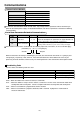
Communications Communications Method RS232C Full-duplex, asynchronous communication method Communications baud rate Data Parity 2400, 4800, 9600bps 8 bit No 1 bit 1 bit Start bit Stop bit Set RS232C communications baud rate with Pr0C. Any change to these parameters will be valid when you power on the control power supply. For detailed information, refer to list of parameters related to the following communications: List of User Parameters Related to Communications Parameter Name PrNo.
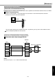
[Reference] Transmission Sequence Transmission Protocol RS232C Host MINAS-E (1) ENQ (05h) (2) EOT (04h) STATUS (3) Data Block Received Data (4) ACK (06h) ALM CODE x6 x5 (or NAK (15h)) (5) ENQ (05h) x4 (6) EOT (04h) x3 (7) Data Block Transmitted Data (8) ACK (06h) x1 (or NAK (15h)) Line Control Direction of transmission and conflict are solved. Reception mode …The module enters reception mode after receiving ENQ and returning EOT.
Communications Configuration of Data Block A data block to be transmitted in physical phase is configured as illustrated below: 1 byte N axis mode command Parameter (N bytes) check sum N : This is the number of command bytes (0 - 240), which indicates the number of parameters needed by a command. axis : This defines a module ID assigned to parameter No.00 axis name of the driver. (1 - 15) command : This is the control command (0 - 15).
[Reference] Example of Data Communication Example of Changing Parameters The following illustrates time-series communications data flow when a change is made to a parameter. Communications should be conducted in the sequence of outline, (1) individual writing of parameters and (2) writing to EEPROM if storage is needed. In this example of hardware connection, the device is directly connected with a host through RS232C communications with user ID=1. Data is represented in hexadecimals.
Communications State Transition Diagram RS232C Communications Transmitting Module EOT is received. Size Number of command bytes + 3 T2 stop Size Number of command bytes - 1 Waiting for EOT Transmission of block ENQ is received and in slave mode. There are requests for transmission (within the number of retries). One character is received. ENQ is returned to receiving buffer (To reception processing) T2 timeout Size becomes zero. The number of retries is counted once.
[Reference] Communications Timing RS232C Communications T3 Host T4 T5 T3 T4 Driver Data block Request for transmission Driver Host ACK/NAK Permission to transmit T3 Host T5 T3 T4 T5 Driver Permission to transmit Driver ACK/NAK Host Request for transmission Data block Code T3 Name Continuous inter-character time Minimum Stop bit length Maximum Protocol parameter T1 T4 T5 Driver response time Host response time 4ms 2ms Protocol parameter T2 Protocol parameter T2 The tim
Communications List of Communications Commands command 0 1 2 8 9 B mode 1 5 6 1 0 1 2 4 5 6 7 8 9 A 0 1 4 0 1 2 3 4 0 1 2 Description NOP Readout of CPU version Readout of the driver model name Readout of the motor model name INIT Setting of protocol parameters POS, STATUS, I/O Readout of status Readout of the command pulse counter Readout of the feedback pulse counter Readout of current speed Readout of current torque output Readout of the current deviation counter Readout of input signal Readout o
[Reference] command 0 mode 5 Readout of the driver model name Received data Transmitted data 0 axis 0Dh axis 5 0 5 0 Driver Model Name (high order) checksum Driver Model Name (low order) Error code checksum Error code bit7 0 : Normal 1 : Error 6 5 Command error 4 3 2 1 0 The driver model name is 12 characters and transmitted by ASCII code. ex.
Communications command 2 mode 0 Readout of status Received data Transmitted data 0 axis 3 axis 0 0 2 checksum 2 Control mode Status Error code checksum Status bit7 Error code bit7 0 : Normal 1 : Error 6 6 5 4 3 CCW CW CCW Torque being output Torque being output rotating 5 Command error 4 3 2 1 0 Torque being Less than DB permission speed limited CW rotating 2 1 0 The control modes are defined as follows: 0 1 2 command 2 High speed response positioning control mode Internal velocity c
[Reference] command 2 mode 2 Readout of the feedback pulse counter Received data Transmitted data 0 axis 5 axis 2 2 2 checksum 2 Counter value L H Error code checksum Error code bit7 0 : Normal 1 : Error 6 5 Command error 3 4 2 1 0 A current position of the feedback pulse counter is expressed by absolute coordinates from the start-up time. For the counter value, "-" indicates CW and "+" indicates CCW.
Communications command 2 mode 6 Readout of the current deviation counter Received data Transmitted data 0 axis 5 axis 6 6 2 checksum 2 Data (deviation) L H Error code checksum Error code bit7 0 : Normal 1 : Error 6 5 Command error 4 3 2 1 0 This command is used to read a current value of the deviation counter. (unit [pulse]) An output value is 32 bits. "+" indicates that the encoder is in CW direction and "-" indicates that the encoder is in CCW direction relative to the position command.
[Reference] command 2 mode 8 Readout of output signal Received data Transmitted data 0 axis 7 axis 8 8 2 2 checksum Data L Data H Warning data Warning data bit7 Overload bit5 Over-regeneration bit0 Battery Error code bit7 0 : Normal 1 : Error 6 L H Error code checksum 5 Command error 4 3 2 1 0 Data bit7 Reserved 6 Reserved 5 Torque being limited 4 Zero speed detected 3 Electromagnetic brake released 2 Positioning completed 1 Servo alarm 0 Servo ready bit15 Reserved 14 Reserved
Communications command 2 mode A Readout of status/input signal/output signal Received data Transmitted data 0 axis 0Dh axis A A 2 checksum 2 Control mode Status Input signal L Input signal H Output signal L Output signal H Warning data L Warning data H Error code checksum Error code bit7 0 : Normal 1 : Error 6 5 Command error 4 3 2 1 0 Meanings of each bit for control mode, status, input signal, output signal, and warning data are same as those of command No.
[Reference] command 8 mode 0 Individual readout of parameters Received data Transmitted data 1 axis 3 axis 0 0 8 Parameter No. checksum Error code bit7 0 : Normal 1 : Error command 8 6 mode 1 5 Command error 4 3 No. error 2 1 Received data Transmitted data 3 axis 1 axis 8 1 Parameter No.
Communications command 9 mode 0 Readout of current alarm data Received data Transmitted data 0 axis 2 axis 0 0 9 checksum Error code bit7 0 : Normal 1 : Error 6 5 Command error 9 Alarm No. Error code checksum 4 3 2 1 0 Alarm No. is 0 when no alarm is generated. (Refer to “Details of Protective Function” on Page 145.) command 9 mode 1 Individual readout of alarm history Received data Transmitted data 1 axis 3 axis 1 1 9 History No.
[Reference] command 9 mode 3 Alarm history clear Received data Transmitted data 0 axis 1 axis 3 9 3 checksum Error code bit7 0 : Normal 1 : Error 6 Data error 5 Command error 9 Error code checksum 4 3 2 1 Control LV 0 The command clears history of alarm data. When the command fails to clear, data error occurs. When control power supply LV is detected, control LV of error code will be returned, and parameter writing will be disabled.
Communications command B mode 0 Individual readout of user parameters Received data Transmitted data 1 axis 9 axis 0 0 B Parameter No. checksum Attribute bit7 Unused parameter bit15 Error code bit7 0 : Normal 1 : Error command B 6 Display inhibited 5 For privileged users B Parameter value L H MIN value L H MAX value L H Attribute L H Error code checksum 3 System related 4 To be changed at initialization 2 1 14 13 12 11 10 9 6 5 Command error 4 3 No.
[Reference] command B mode 2 Page writing of user parameters Received data Transmitted data 21h axis 2 axis 2 B Page No. Parameter L (No.0 value) H Parameter value (No.1 value) ~ Parameter value (No.0fh value) checksum Error code bit7 0 : Normal 1 : Error 6 Data error 5 Command error 4 2 B Page No. Error code checksum L H L H 3 No. error 2 1 0 The command writes 16 parameters at once. Be sure to set 0 to unused parameters. Otherwise, data error will occur.
Description on Dividing/Multiplier Ratio Relation between Positional Resolution/Moving Speed and Command Dividing Multiplier Ratio Servo driver Command dividing multiplier ratio Pulse row position command D= Distance: P1 [P] Traveling speed: F [PPS] Pr46 x 2 Pr4B Rotation speed: N [r/min] Pr4A Servo motor Gear Machine Reduction ratio: R Encoder Number of encoder pulses E [P/r] 10000 = (phase A/B 2500 [P/r] x 4) Example of driving ball screw using the servo motor As an example of a machine, we descr
[Reference] Example 1 2 Command dividing multiplier ratio Lead of ball screw L = 10mm Reduction ratio R=1 Position resolution ∆M = 0.005mm For the encoder of 2500 P/r (E=10000P/r) D= Lead of ball screw L = 20mm Reduction ratio R=1 Position resolution ∆M = 0.005mm For the encoder of 2500 P/r (E=10000P/r) D= ∆M x E x R L Pr46 x 2 Pr4B 0.005 x 10000 x 1 10 0.0005 x 10000 x 1 20 D<1 is not appropriate to determination of the accuracy. = 0.25 Motor rotation speed (r/min) 0.
Conformance to EC Directives/UL Standards EC Directives The EC Directives apply to all such electronic products as those having specific functions and directly sold to general consumers in EU countries. These products are required to meet the EU unified standards and to be furnished with CE Marking. However, our AC servo meet the EC Directives for Low Voltage Equipment so that the machine or equipment comprising our AC servo can meet relevant EC Directives.
[Reference] Peripheral Equipment Environment The servo driver should be used under Contamination Level 2 or 1 specified by IEC60664-1 (housing the driver in an IP54 control box).
Conformance to EC Directives/UL Standards Noise Filter When, one set of noise filters is installed in the power unit with two or more drivers, be sure to consult with the noise filter manufacturer. Option Part No. Manufacturer’s part No. DV0P4160 3SUP-HU10-ER-6 Manufacturer Okaya Electric Industries Co., Ltd. Surge Absorber Install the surge absorber on the primary line of the noise filter. When conducting voltage-resistant test on the machine/equipment, remove the surge absorber.
[Reference] Noise Filter for Signal cables Provide all the cables (power supply cable, motor cable, encoder cable, interface cable) with the noise filter for signal cable. Option Part No. Manufacturer’s part No. Manufacturer DV0P1460 ZCAT3035-1330 TDK Co., Ltd. Weight: 62.8 g Grounding (1) Don’t fail to connect the servo driver protective earth terminal ( ) and the protective earth plate of the control panel together. (2) When connecting to the protective earth terminal ( ), avoid co-clamping.
Optional Parts MINAS-E Series Table of Junction Cable by Model Figure No. Motor Type Junction Cable For an encoder (2500 P/r 5 wires) 2-1 MUMA50W - 400W 3-1 4-1 Incremental For a motor For a brake Part No. MFECAO * * OEAM MFMCAO * * OAEB MFMCBO * * OGET Junction Cable for Encoder Figure 2-1 MFECA0 * * 0EAM L (16) (ø9.2) (20) (4) (14) (4) Manufactured by Tyco Electronics AMP K.K. Connector Pin L (m) Part No.
[Reference] Connector Kits for Power Supply of the Driver (1) Part No. DV0P2870 (2) Components Name Manufacturer’s part No. Number Manufacturer Remarks Connector (10P) Connector Pin 5557-10R-210 5556PBTL 1 6 Molex Incorporated For connector CN X1 (pin 10) (3) Pin arrangement of connector for CN x 1 10 L1 5 P 9 (NC) 4 (NC) (4) Recommended manual pressure bonding tool (Customers are requested to provide it by themselves.) 8 L2 3 B 7 (NC) 2 (NC) 6 L3 1 E Manufacturer’s part No.
Optional Parts Connector Kits for Connection of Motor and Encoder Used for: MUMA 50W to 400W Incremental 2500 pulse 5-wire (1) Part No. DV0P3670 (2) Components Name Manufacturer’s part No. Number Manufacturer Remarks For connector CN X4 (pin 6) Connector 55100-0600 1 Molex Incorporated Connector (6P) 172160-1 1 Connector pin Connector (4P) 170365-1 172159-1 6 1 Manufactured by Tyco Electronics AMP K.K. Manufactured by Connector pin 170366-1 4 Tyco Electronics AMP K.K.
[Reference] (5) Pin arrangement of connector for junction of encoder cable 1 (NC) 4 +5V 2 TX/RX 5 0V 3 TX/RX 6 FG (6) Pin arrangement of connector for junction of motor power line 1 U 3 W 2 V 4 E (7) Pin arrangement of connector for connector CN X3 6 W 3 E 5 (NC) 2 (NC) 4 V 1 U 1. The above table shows arrangement of pins viewed from the pin inserting direction of the connector. Also check pin Nos. carved on the main body of the connector so as to avoid incorrect wiring. 2.
Optional Parts Connector Kit for Connection with Host Controller (1) Part No. DV0P0770 (2) Components Name Manufacturer’s part No.
[Reference] Communications Cable (Connection with Personal Computer) (1) Part No. DV0P 1960 (for DOS/V compatible machines) 2000 33 18 Mini DIN8P MD connector D sub connector 9P For pin arrangement of CN X6, see Page 159. “PANATERM®”, software for communications control (1) Part No. DV0P4230 (Japanese version) DV0P4240 (English version) (2) This is supplied in the form of a 3.5 inch floppy disk.
Optional Parts External Regenerative Resistor Manufacturer’s Part No. model name Specification Operating Temperature for Ohmic Value Rated Power Built-in Temperature Fuse Remarks (Specifications for the driver voltage) DV0P2890 45M03 50 Ω 10W 130±2˚C For single-phase 100V DV0P2891 45M03 100 Ω 10W 130±2˚C For single-phase/ three-phase 200V Manufactured by: IWAKI MUSEN KENKYUSHO CO., LTD. For safety reasons, the external regenerative resistor has a built-in temperature fuse.
[Reference] Reactor 2-I Figure 1 Reactor Part No.
Recommended Parts Surge Absorber for Motor Brake Motor Surge Absorber for Motor Brake MUMA50W - 400W • C-5A2 or Z15D151 Ishizuka Electronics Corporation • The recommended parts are specified items to measure the brake release time. List of Manufacturers of Peripheral Equipment As of February 2003 Manufacturer/Agent Matsushita Electric Works, Ltd. Automation Controls Company Phone Number Equipment No-fuse breaker +81-6-6908-1131 http://www.mew.co.
Dimensional Outline Drawing Driver (Frame K) Estimated Mass 0.35 kg Driver (Frame L) Estimated Mass 0.
Dimensional Outline Drawing Motor MUMA Series 50W to 400W LR LL LE LBh7 Sh6 200 LG LF Output LG 50W, 100W 230mm 200W, 400W 220mm (Unit: mm) Without a brake With a brake MUMA Model Output (W) LL S LB LE 8 22 2 MUMA5A P1 50 75.5 MUMA01 P1 100 92.
[Reference] Shaft-end Center Tap TP Specification of Keyed Version (Dimension) Output 50W, 100W Screw M3 Depth 6 200W M4 8 400W M5 10 LC LZ LW LK KW KH RH LH Without a brake MUMA LA 48 42 3.4 14 12.5 3 3 6.2 34 With a brake (Unit: mm) 48 20 70 60 42 60 4 4 8.5 43 3.4 25 22.5 5 5 11 14 12.5 3 3 6.2 20 70 18 4.5 18 4 4 Mass (kg) Rotor Moment of Inertia (x10-4kg·m2) 0.40 0.021 0.50 0.032 0.96 0.10 1.5 0.17 0.60 0.026 0.70 0.036 1.4 0.13 1.
Dimensional Allowable Load Outline of Output Drawing Shaft Radial Load Direction (P) Thrust Load Directions (A, B) LR A M B LR/2 P Unit: N (1kgf = 9.8N) Motor Series MUMA When Assembled Motor Output 50W, 100W 200W, 400W In Operation Thrust Load Thrust Load Radial Load Radial Load Directions A, B Direction A Direction B 58.8 147 88.2 117.6 68.
Motor Characteristics (S-T Characteristics) [Reference] Note that motor characteristics may vary depending on whether or not there is a brake. The continuous torque — ambient temperature characteristic shows a value when our standard flange made of aluminum (having about doubled angle of that of the motor flange) is mounted. They are characteristics without an oil seal.
Servo Motor with Gear Checking Model of Servo Motor with Gear How to check the model M U M A 1~4 Symbol MUMA 0 1 1 5~6 7 P 3 1N 8 9 10 Reduction Ratio Type Symbol Reduction Ratio Ultra low Inertia Structure of the motor Motor Rated Output Symbol Rated Output 100W 01 200W 02 400W 04 Specifications of Position/Speed Detector Rated Output Voltage Specification 1 : 100V 2 : 200V Specification of Rotary Encoder Specification Symbol Number of Pulses Resolution Lead Wire Method 2500P/r Increment
[Reference] Check the Combination of Driver and Motor with Gear This driver was designed for use with the motor designated by us. Check a name of the series, rated output, voltage specification, and encoder specification of the motor you plan to use. Incremental Specification 2500 P/r You must not use any combination other than those listed below.
Dimensional Outline Drawing of Motor with Gear Servo Motor with Gear * 220 refers to 200W or higher. (unit: mm) Model Motor Reduction Ratio Output 1/5 MUMA01 P31N Without a brake MUMA01 P32N 192 234,5 1/5 200.5 1/9 235.5 MUMA02 P34N 1/25 246 MUMA042P31N 1/5 MUMA02 P31N MUMA02 P32N 200W 400W 1/5 MUMA01 P41N MUMA01 P42N 1/9 1/25 MUMA042P34N 100W 1/9 263 223.5 1/5 233.5 1/9 268.
[Reference] Detailed View of Shaft End (unit: mm) With a brake MUMA Without a brake LC LA LZ LD Key Dimensions (B × H × LK) T LN Mass (kg) Moment of Inertia (×10-4kg m2) 0.072 52 60 M5 12 4 × 4 × 16 2.5 78 90 M6 20 6 × 6 × 22 3.5 2.20 0.0645 52 60 M5 12 4 × 4 × 16 2.5 1.68 0.218 1.05 34 2.66 78 90 M6 20 6 × 6 × 22 3.5 43 3.2 0.533 3.2 0.438 0.470 4.7 12 4 × 4 × 16 2.5 1.25 M6 20 6 × 6 × 22 3.5 2.40 0.0685 M5 12 4 × 4 × 16 2.5 2.08 0.
Allowable Load of Output Shaft of Servo Motor with Gear Radial Load (P) Direction Thrust Loading (A, B) Direction LR A M B LR/2 P Unit: N Shaft Allowable Load Thrust Load Radial Load A, B directions Motor Output Gear Ratio 100W 1/5 1/9 490 588 245 294 1/25 1670 833 1/5 1/9 490 1180 245 588 1/25 1670 833 1/5 1/9 980 1180 490 588 1/25 2060 1030 200W 400W Requests Concerning Installation (1) (2) (3) (4) Do not tap on the shaft when mounting the pulley, sprocket, etc.
Characteristics of Servo Motor with Gear (S-T Characteristics) Reduction Driver Ratio Supply Motor Voltage Output 1/5 1/9 Torque 4.0 3.72 2.0 Torque 20.0 19.0 6.86 Instant Operation Area Instant Operation Area 4.0 1.18 10.0 6.27 2.25 Continuous Operation Area 0 1/25 Torque 8.
204 Pulse Output Control Output Control Input Pulse Row Command Alarm Signal CN X5 CN X6 External Regenerative Resistor B P L1 L2 L3 Dividing/ Multiplier N + - +3.
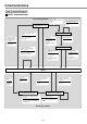
Pr42 Input Mode Setting Reference 205 Feedback Pulse (OZ•CZ) Feedback Pulse (OA•OB) PULS SIGN Pulse Row Command PANATERM Monitor Total of Command ulses Pr4E FIR Filter Command Dividing/ Multiplier Numerator Pr46 Scale Pr4A Numerator 2 Denominator Pr4B Pr4C Pr53 Pr54 Pr55 Pr56 Internal 2nd Speed Internal 3rd Speed Internal 4th Speed Inversion Pr45 Dividing Pr44 Speed Setting Internal/ External Switching - + Waveform Graphic Position Deviation + + Waveform Graphic Command Speed Pr18 2n
Specifications Power Supply Single-phase 100V Single-phase AC100V Single-phase 200V Single-phase AC200V Three-phase 200V Three-phase AC200V Driver Allowable frequency variations Control method Detector Specification of applicable rotary encoder Regeneration Dynamic brake Auto gain tuning Built-in functions Electronic gear (Dividing/multiplier of a command pulse) Dividing of feedback pulse Protective Function Monitor Setting Position Control Motor Velocity Control Capable of storing 14 alarms inc
Hit-and-stop Initialization and Load Pressing Control [Reference] Hit-and-stop Initialization When you find it difficult to install a sensor as the surroundings are not good, Hit-and-stop Initialization can be used.
Hit-and-stop Initialization and Load Pressing Control Load Pressing Control Example of Application PrNo.
Index [Reference] A Items Terms Adjustment Real time Auto Gain Tuning (Position Control Mode) Real time Auto Gain Tuning (Velocity Control Mode) Gain Adjustment Normal Auto Gain Tuning Cancellation of the Automatic Gain Tuning Manual Gain Tuning To Reduce Mechanical Resonance Adaptive Filter Gain Switching Function Anti-Vibration Control page 86 114 128 132 135 136 140 131 138 142 Alarm Code Protective Functions 144 Driver Model Designation Name plate Combination of Driver and Motor Check the Co
Index D Items Terms Display (Monitor) Monitoring Mode EEPROM Writing Mode Parameter Setting Mode Normal Auto Gain Tuning Mode Alarm Clear page Dividing-Multiplier Description on Dividing/Multiplier Ratio 51 50 57 58 59 178 E Items Terms Encoder Incremental specification 2500P/r page 15 H Items Terms Hit-and-stop Homing Operation Hit-and-stop Initialization Homing Operation (Precautions) page 207 38 I Items Terms International Standards EMC Directives EC Directives Peripheral Equipment
[Reference] O Items Terms page Option Noise Filter Surge Absorber Noise Filter for Signal cables Table of Junction Cable by Model Junction Cable for Encoder Junction Cable for Motors Junction Cable for Brakes Communications Cable (Connection with Personal computer) [PANATERM®], Software for Communications Control Connector Kits for Connection of Motor and Encoder Connector Kit for Connection with Host Controller Interface Cable for Connection with Host Controller External Regenerative Resistor Reactor C
Index R Items Terms page Recommended Parts Surge Absorber for Motor Brake 192 S Items Terms Safety Precautions Safety Precautions Maintenance and Inspection page Servo Motor with Gear Model Designation Checking the Combination of the driver and the motor with gear Dimensional Outline Drawing of Motor with Gear Allowable load of Output Shaft of Servo Motor with Gear Characteristics of Servo Motor with Gear (S-T Characteristics) 8 12 14 199 200 202 203 T Items Terms page Test Run Inspection
[Reference] W Items Terms page Wiring Installation of Driver Installation of Motor General Wiring Diagram Wiring of Main Circuits Wiring Diagrams Connection with Encoder Connection with Personal Computer/Console Connection with Host Controller Wiring in Position Control Mode Wiring in Velocity Control Mode 18 20 24 27 28 29 31 30 67 105 Reference 213
Reference Motor Company, Matsushita Electric Industrial Co., Ltd.
[Reference] MEMO Reference 215
After-Sale Service (Repair) Repair • Ask the seller where the product was purchased for details of repair work. When the product is installed in a machine or device, consult first the manufacture of the machine or device. Cautions for Proper Use • This product is intended to be used with a general industrial product, but not designed or manufactured to be used in a machine or system that may cause personal death when it is failed.