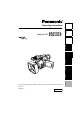
Camera-Recorder AG- P Before use Preparation Model No. Description of parts Operating Instructions Before operating this product, please read the instructions carefully and save this manual for future use F0805S0 -H ENGLISH VQT0U08 Reference Menus Displays Editing Playback Shooting .
CAUTION RISK OF ELECTRIC SHOCK DO NOT OPEN CAUTION: TO REDUCE THE RISK OF ELECTRIC SHOCK, DO NOT REMOVE COVER (OR BACK). NO USER-SERVICEABLE PARTS INSIDE. REFER TO SERVICING TO QUALIFIED SERVICE PERSONNEL. The lightning flash with arrowhead symbol, within an equilateral triangle, is intended to alert the user to the presence of uninsulated “dangerous voltage” within the product’s enclosure that may be of sufficient magnitude to constitute a risk of electric shock to persons.
Important Safeguards 1. Read Instructions — All the safety and operating instructions should be read before the unit is operated. 2. Retain Instructions — The safety and operating instructions should be retained for future reference. 3. Heed Warnings — All warnings on the unit and in the operating instructions should be adhered to. 4. Follow Instructions — All operating and maintenance instructions should be followed. 5. Cleaning — Unplug this video unit from the wall outlet before cleaning.
Important Safeguards (continued) 13. Outdoor Antenna Grounding — If an outside antenna or cable system is connected to the video unit, be sure the antenna or cable system is grounded so as to provide some protection against voltage surges and built-up static charges.
Contents Before use Shooting Important Safeguards ................................... 3 Read this first!................................................ 7 Accessories.................................................... 7 Operating precautions................................... 8 Checking the system operations................ 10 Items to prepare.............................................. 10 Connect the AC power supply cord ............... 10 Insert the Mini DV cassette tape.....................
Contents (continued) Playback Menus Playback ....................................................... 48 Using the setup menus ...............................66 Adjusting the volume ...................................... 49 Viewing images on a television .......................49 Checking the date and time ............................ 49 Using the setup menus ................................... 66 Initializing the menu settings .......................... 67 Variable-speed playback ....................
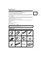
Read this first! • When shooting important events (such as weddings), always take some trial shots and check that the sound and images have been recorded properly before actual shooting. Panasonic makes no guarantees for your recordings. • Please understand that Panasonic makes no guarantees for your recordings in cases where images and/ or sound were not recorded as you intended due to problems with the camera-recorder or cassette. Before use Always take some trial shots before actual shooting.
Operating precautions Do not allow any water to get into the camera-recorder when using it in the rain or snow or at the beach. • Failure to heed this caution will cause the camerarecorder or cassette to malfunction (and may result in irreparable damage). Keep the camera-recorder away from equipment (such as TV sets and video game machines) that generate magnetic fields.
Remove the battery after use Completely remove the battery. (The battery continues to be used even if you have turned the camera off.) The battery can over discharge if you leave it in the camera and it may become impossible to recharge it. Disposing of spent batteries • The battery will become unchargeable. Rather than throwing the battery into the garbage, take it to a store that can assist in recycling it. Protect the battery terminals.
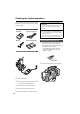
Checking the system operations After purchase, do these system checks to ensure that the unit is working properly before you attempt to shoot anything. Items to prepare AC adapter AC power supply cord DC cord Mini DV cassette tape Connect the cords properly as shown in the figure above. • You cannot charge the battery when supplying power to the camera-recorder from the AC adapter. CAUTION: • This unit will operate on 110/120/220/240 V AC.
Press PUSH to close the cassette holder. The holder automatically goes into position when you close it correctly. Start shooting Before use 3 Viewfinder PUSH POW ER ON OFF PUSH 1 2 • Do not try to insert or eject the tape by just holding the cassette cover. • Insert and remove cassette tapes after putting the camera-recorder down on a stable, flat surface or hold it with both hands to keep it stable. • Do not force the cassette holder while it is moving. Trying to do so could damage the camera.
Checking the system operations (continued) Check what you have shot (rec check) 1 Press the OPEN button in the direction shown by arrow (1) to open the LCD. It can open out to 120 degrees. Do not try to open it further as this will damage the camera. Eject the tape 1 Slide the EJECT switch in the direction shown by the arrow to open the cassette cover. When the cassette cover is fully open, the cassette holder automatically opens out.
POW CAMERA ER ON OFF Before use Turn off the unit VCR Lock release While pressing the lock release, move the POWER switch to OFF. The red CAMERA lamp goes out. Disconnect the power cord Battery release 1 2 3 4 Unplug the AC cord from the power outlet. Lift up the viewfinder. While pressing the battery release, pull the DC cord’s battery connector towards you. Return the viewfinder to its original position.
Adjusting the hand strap Adjust the hand strap to suit your hand. 1 2 Open the cover and adjust the length. Close the cover. • Make sure the cover is fully closed. Attaching the shoulder strap Attach the shoulder strap and use it as a precaution against dropping the camera.
Detaching the lens hood Mark • Loosen the screw and turn the lens hood counterclockwise to detach it. Attaching the lens hood Before use Attaching the lens hood Screw • Position the lens hood so the mark is at the top and fit it onto the lens. • Turn the lens hood clockwise and fix in position with the screw. Attaching the lens-cap strap Thread the strap through the lens cap. Thread one end through the hand strap. Cassette tapes g Use the following mini DV cassette tapes with this camera-recorder.
Description of parts Camera-recorder 1 3 2 5 7 4 6 9 15 16 8 POW ER ON OFF 14 Bottom 13 PUSH 10 11 12 17 18 1 POWER switch (Page 11) 17 Power terminals (Page 10) 2 START/STOP button (Page 11) 18 DC INPUT terminal (7.9 V) 3 Rear tally lamp (Page 82) 19 Battery release (Pages 13 and 22) 4 Rear remote control sensor 5 REC CHECK button (Page 12) 6 Zoom button (Page 32) 7 HANDLE ZOOM switch (Page 32) 8 Handle zoom button (Page 32) 9 Handle START/STOP button (Page 33) 10 PHONES jack (3.
20 22 24 26 23 25 27 Description of parts 21 AWB 29 28 31 30 33 32 20 Focus ring (Page 38) 21 Zoom ring (Page 32) If you don’t need the zoom ring pin, fit it into the provided hole (23) so that you don’t lose it.
Description of parts (continued) 40 42 44 41 46 43 50 49 45 52 51 54 53 48 56 59 58 47 65 61 60 63 62 67 66 55 64 69 68 40 LCD monitor (Pages 9 and 24) 57 S-VIDEO IN/OUT terminal (Page 55) 41 RESET button (Page 24) 58 DV terminal (Page 36) 42 DISPLAY/AUDIO DUB button (Pages 56 and 65) 59 VIDEO IN/OUT terminal (pin jack) (Page 55) 43 VCR REC buttons (Pages 58 and 60) 61 Light shoe 44 AUDIO MON/VAR buttons (Pages 49, 50, and 51) 62 Built-in stereo microphone (Page 44) 45 SHUTT
Remote control The following buttons are for functions that cannot be executed on the camera-recorder. 1 DATE/TIME button (Page 49) • • • • 3 COUNTER button Same function as the COUNTER button on the main unit. 2 OSD button(Page 49) • TITLE • SELECT • OFF/ON 4 COUNTER RESET button Same function as the COUNTER RESET button on the main unit. Description of parts PHOTO SHOT MULTI/P-IN-P STORE PB.ZOOM 5 A.DUB button Same function as the AUDIO DUB button on the main unit.
The remote control Insert the battery 1 Push the catch in the direction shown by arrow (1) to remove the holder. Remote control setup When using two camera-recorders simultaneously, set this camera-recorder and the remote control to either [VCR1] or [VCR2] so the remote control does not operate the wrong camera-recorder by mistake. Setting • Wireless remote control 2 Insert the battery with the “+” marked side facing up.
The battery Charging 1 Align the battery with the “ ” marking on the AC adapter, place it flat, and slide it in the direction shown below. • You cannot charge the battery if the DC cord is connected to the DC OUT connector, so disconnect it first. Recording time of included battery Recharging time Continuous recording time Approx. 330 min. Approx. 360 (or 300) min. • Times given above are approximate. Figures in parentheses show the recording times when you use the LCD monitor.
The battery (continued) Attaching the battery 1 2 3 Lift up the viewfinder. Press on the battery and move it down until it clicks into place. Return the viewfinder to its original position. Detaching the battery • Turn POWER to OFF and check that the POWER lamp (CAM/VCR) has gone off before detaching the battery. • Support the battery with your hand so that it does not fall. While pressing the battery release, lift the battery out.
Viewfinder • The brightness and hue may differ between the images appearing on the viewfinder and LCD monitor and those displayed on a TV monitor. To see how the final images will appear, check them on a TV monitor. Fitting the eye cup Attach the eye cup by aligning the projections on the eye cup holder and eye cup and fitting them together. • Turning the eye cup after attaching it may cause the eye cup holder to come off.
Viewfinder (continued) Using the LCD 1 2 Set the POWER switch to ON. Press the OPEN button in the direction shown by arrow (1) to open the LCD. It can open out to 120 degrees. Do not try to open it further as this will damage the camera. Emphasizing outlines Emphasizing the outlines of the images you see in the viewfinder or on the LCD makes it easier to focus. Emphasizing the outlines does not effect the images you shoot. 1 In CAMERA mode, press EVF DTL/END SEARCH.
Adjusting the screen display To adjust the viewfinder’s screen: In the setup menus, DISPLAY SETUP screen EVF SET, select YES. To adjust the LCD’s screen: In the setup menus, DISPLAY SETUP screen LCD SET, select YES. • For menu operation (Page 66) • You can also use the menu buttons on the remote control. (Page 19) 4 Select EVF CONTRAST and move the OPERATION lever t or y to adjust the contrast of the screen.
Time data Setting the calendar This shows you how to adjust the calendar to 5:20 PM on December 25, 2005. 1 5 Move the OPERATION lever t or y to set the MONTH to DEC. CLOCK SET Set the POWER switch to ON. POW YEAR 2005 MONTH DEC DAY 24 HOUR 13 7 MIN ER ON OFF 2 +/- : PUSH REW/FF SEL : PUSH PLAY/STOP In the setup menus, OTHER FUNCTIONS screen, CLOCK SET, select YES. • For menu operation (Page 66) • You can also use the menu buttons on the remote control.
1 2 3 4 Press the OPERATION lever [h] (or move it y), move it r to select YES and press [h] again. RECORDING SETUP ---USER TC PRESET UB MODE UB PRESET ONE-SHOT REC REC TIME Connect the AC adapter. (Page 10) YES 0.5S Leave the POWER switch at OFF. PUSH MENU TO RETURN Leave the camera-recorder like this for about 4 hours. • The internal battery charges during this time. • Recharge the battery regularly to ensure correct TC and menu operations.
Time data (continued) You can reset user information to nothing by pressing COUNTER RESET. DATE/ TIME MULTI/ P-IN-P /REW Camera 6 or REC PLAY PHOTO SHOT START/ STOP TITLE A.DUB ZOOM - VOL + OSD COUNTER RESET FF/ Remote control Press the MENU button when you have finished setting the user information. MENU 7 The following screen appears, so move the OPERATION lever e to select YES. UB PRESET PRESET OK? ___ YES NO 8 PUSH STILL Press the OPERATION lever [h].
Specifying the time code (TC PRESET) Set TC PRESET so you can record a value of your choice as the initial setting for the time code to be used at the start of recording. 1 Set the POWER switch to ON. POW ER ON OFF 5 The following screen appears, so use the OPERATION lever to set the time code. TC PRESET 00h00m00s00f +/- : PUSH PLAY/STOP SEL : PUSH REW/FF 2 In the setup menus, RECORDING SETUP screen FIRST REC TC, select PRESET.
Time data (continued) 6 Press the MENU button when you have finished setting the time code. MENU 7 The following screen appears, so move the OPERATION lever e to select YES. TC PRESET PRESET OK? ___ NO YES 8 PUSH STILL Press the OPERATION lever [h]. TC PRESET PRESET OK? YES NO 9 PUSH STILL Press MENU twice to exit the menus.
Regular shooting 1 2 g Cassette tape (Pages 10 and 15) Check that the cassette tape can be used for recording. • Set the erasure prevention tab to SAVE. • Make sure the tape doesn’t have images you want to keep recorded on it. • Make sure the cassette holder is completely closed. appears on the viewfinder and LCD screens. AUTO button The camera makes the following adjustments for you when in auto mode. g Viewfinder (Page 23) See if the diopter adjustment is suitable.
Shooting techniques for different targets Check what you have shot (rec check) Zoom Press REC CHECK in the shooting standby mode and two seconds of the last thing you shot play, and then the camera returns to the shooting standby mode. This camera has a 10 x zoom. Zoom with the zoom button or the zoom ring. • REC CHECK does not work if you have shot for less than a second. • Note that this REC CHECK portion will also be recorded to any equipment you have set up to make backup recordings.
Low-angle shooting Use the START/STOP button on the handle to make it easier to shoot from low angles. START/STOP button Zebra pattern Press the ZEBRA button in the camera mode to show the zebra pattern or marker on the screen so you can check the brightness of the subject. Parts that may be whited out through over exposure are shown as a zebra pattern.
Shooting techniques for different targets (continued) ONE-SHOT recording 1 2 3 4 In the setup menus, RECORDING SETUP screen, ONE-SHOT REC, select ON. • For menu operation (Page 66) OFF: ONE-SHOT is off. ON: The camera records for the number of seconds you have set in REC TIME, then returns to shooting standby mode. • While in progressive mode 24P or 24P (ADV) you cannot change ONE-SHOT settings. Changing the image size You can change the aspect ratio of the images you record with this camera.
Optical Image Stabilizer Use the Optical Image Stabilizer (OIS) to reduce the effects of camera shake when shooting by hand. Press the OIS button to turn the function on and off. appears on the screen when this function is on. Turn the function off when using a tripod for more natural images. Index recording Press the USER button you have allocated to the INDEX feature during shooting and an index signal is recorded to the tape.
Shooting techniques for different targets (continued) Backup recording If you have connected equipment to the DV terminal (Page 54). You can make automatic backup recordings of whatever you are shooting. • In the setup menus, OTHER FUNCTIONS screen, DV CONTROL and DV CMD SEL, select how to control the equipment you have connected. (Page 77) Note the following when backup recording. • Menu settings are retained even if you turn the power off.
Shooting in progressive mode 30P mode: Shoot 30 frames a second in the progressive mode. For output and recording, the 30-frame-persecond signal is converted to 60-field-persecond interlace. This mode gives you high quality images. 30 P A B C D E F G H I J 60 i AoAeBoBeCoCeDoDeEoEe Fo FeGoGeHoHe Io Ie Jo Je 24P mode: Shoot 24 frames a second in the progressive mode. For output and recording, the 24-frame-persecond signal is converted to 60-field-persecond interlace using the widely used “2:3” ratio.
Focus This camera allows you to choose between automatic and manual focusing. Focus ring FOCUS switch AUTO button PUSH AUTO button 1 2 If the camera is in auto mode, press the AUTO button to switch to manual focusing ( goes out). Use the FOCUS switch to choose how to control focusing. A (AUTO): Auto focus mode M (MANUAL): Manual focus mode Turn the focus ring by hand. ∞: The camera first focuses on infinity, then it switches to manual focus.
Adjusting the shutter speed Shutter speeds you can select Shutter speeds you can select with SPEED SEL Progressive mode Normal shutter speeds (OFF) SYNCHRO SCAN OFF (60i) 1/60 1/60.3 - 1/250 30P 1/50 1/30.1 - 1/250.0 1/30, 1/60, 1/120, 1/250, 1/500, 1/1000 24P/24PA 1/50 1/24.1 - 1/250.
Shooting techniques for different targets (continued) Slow shutter mode 1 2 In the setup menus, SW MODE screen, allocate one of the USER buttons to SLOWSHUT. (Page 72) PUSH STILL SLOW 1/4 Press the USER button you have allocated to SLOWSHUT to enter the slow shutter mode. Each time you press SPEED SEL, the shutter speed changes as shown below.
Adjusting the white balance When you are shooting in manual mode, readjust the white balance whenever lighting conditions change. You can save adjustments and reselect them by setting the WHITE BAL switch to A or B. You can also use the preset values. Use the settings to suit the shooting conditions. 5 Press the AWB button. • Adjustment takes a few seconds. (The following messages appear on the screen.
Adjusting the white balance (continued) Using presets Use this feature when you have no time to make white balance adjustments. 1 2 3 If the camera is in auto mode, press the AUTO button to switch to manual focusing ( goes out). Set the WHITE BAL switch to PRST. The current white balance value appears. • White balance values 3200 K and 5600 K are preset in the PRST position. Guide to the preset values 3200 K: halogen light 5600 K: outdoors Press the AWB button.
Adjusting Iris, Gain, and Light Intensity IRIS dial ND FILTER switch Adjusting the gain When the display is dark, increase the gain to brighten the display. 1 2 IRIS button GAIN switch Iris adjustments 1 2 3 If the camera is in auto mode, press the AUTO button to switch to the manual mode ( goes out). Switch the gain with the GAIN switch. L: Set here under normal conditions. (0 dB) M: Increase the gain of the image amplifier. (The default value is 6 dB.) H: Increase the gain of the image amplifier.
Switching Audio Input You can record audio through two channels when shooting (see the table below). You can switch the source for each channel between the built-in microphone, another microphone, or audio equipment connected to the camera.
Using scene files Scene file dial Changing scene file settings The setting value of the scene file can be changed. Also you can save the changed scene file to each position of the scene file dial. Example: Change the name of the scene file. 1 2 3 • Progressive mode will not be changed even if you change the scene file while recording. If you want to change the progressive mode, please set the camera-recorder to recording standby state.
Using scene files (continued) 6 The screen below is displayed, so set the file name of six letters using OPERATION lever. Set the same as user information (Page 27). • Characters that can be set Space, A to Z, 0 to 9, : ; < = > ? @ [ \ ] ^_-/. 10 The following screen appears, so press the OPERATION lever (h). FILE F1: SAVE INITIAL NAME EDIT SW POSITION F1 + : PUSH PLAY - : PUSH STOP SEL : PUSH REW/FF PUSH MENU TO RETURN 7 8 After you finish setting the filename, press the MENU button.
Transferring scene files 6 OTHER FUNCTIONS POWER SAVE H.P MODE USER FILE FILE TRANS FILE RECEIVE HOUR METER • You can only transfer between DVX100B models. 1 2 3 4 Connect camera 1 to camera 2 with a DV (IEEE1394) cable. For connection (Page 54) When choosing SCENE (step 7), set the scene dial on camera 1 to the item you want to send, and set the scene dial on camera 2 to the item you want to send it to. (For example you can send F1 to F2.
Playback 1 2 Set the POWER switch to ON. Press the CAMERA/VCR button to switch to VCR mode. 3 Use the OPERATION lever and the supplied remote control to perform the common playback operations (see below). CAMERA VCR Basic operations Remote control /REW FF/ PLAY STILL ADV PAUSE STILL ADV INDEX STOP INDEX -V While the tape is in the stop mode, turn the lever in the direction q to play back.
Adjusting the volume Checking the date and time AUDIO MON/VAR button Press the DATE/TIME button on the remote control to show the date and time of shooting on the screen. The display changes as follows each time you press the button. Time Date OSD Time and Date DATE/ TIME COUNTER RESET PHOTO SHOT TITLE START/ STOP ZOOM MULTI/ 1 With the AUDIO MON/VAR button, adjust the volume of the sound that is output from the internal speaker and PHONES jack. On the remote control, press the ZOOM/VOL button.
Variable-speed playback Slow playback During play, press one of the STILL ADV ( or ) buttons on the remote control unit. -V 1 Fast-forward and rewind /REW PLAY FF/ STILL ADV PAUSE STILL ADV STOP INDEX -V INDEX During playback, move the OPERATION lever y to play 10 times normal speed. During playback, move the OPERATION lever t to rewind at 10 times normal speed. Fast-forward/fast-rewind continue as long as you hold the lever in place.
Variable speed search End search This function enables you to change the playback speed and search for specific scenes. You can find unrecorded parts or the end of the last scene shot. 1 1 During playback, move the OPERATION lever q. On the remote control, press the VAR. SEARCH button. STOP INDEX VAR. SEARCH PB. ZOOM STORE MENU SET OFF/ON P.B.DIGITAL Camera or ITEM Remote control [1x] appears on the screen and the tape is played back at the normal speed. No sound is heard at this time.
Using the Counter Counter display You can display a counter that indicates how much time has elapsed during shooting or playback. COUNTER button or Remote control OSD DATE/ TIME COUNTER RESET MULTI/ P-IN-P /REW REC PLAY TITLE A.DUB ZOOM FF/ COUNTER RESET/TC SET button 1 Press the COUNTER button. Each time you press the button, the display changes as follows. 0 : 00. 00: Counter value M 0 : 00.
Connecting external units Headphones PHONES External microphone Microphone holder Microphone holder Adapter INPUT1 or INPUT2 12 mm Playback Stereo Microphone (optional) AG-MC100G Editing 6 mm • When attaching an external microphone to the microphone shoe, use the supplied microphone holder and microphone holder adapter.
Connecting external units (continued) Digital video equipment This camera Other Digital video equipment 1 SVIDEO IN/OUT CH2 CH1 AUDIO IN/OUT VIDEO IN/OUT DV 2 DV (IEEE1394)cable (optional) 4-pin type g You can connect a digital video unit equipped with a DV connector and digitally transfer video and audio signals as well as time code. • Before proceeding to connect or disconnect DV (IEEE1394) cable, be absolutely sure to turn off the power of the units.
Television SVIDEO IN/OUT SVIDEO DV DV IN/OUT CH2 CH1 CH2 CH1 AUDIO IN/OUT VIDEO IN/OUT AUDIO IN/OUT VIDEO IN/OUT AV cable (optional) AV cable (optional) Red:CH2 (Rch) audio White:CH1 (Lch) audio Yellow: Video Red: CH2 (Rch) audio White: CH1 (Lch) audio Yellow: Video S-video cable (optional) Television with S-video connector Video deck IN/OUT DV SVIDEO IN/OUT CH2 CH1 CH2 CH1 AUDIO IN/OUT VIDEO IN/OUT AUDIO IN/OUT VIDEO IN/OUT DV AV cable (optional) AV cable (optional) Editin
Audio dubbing Background music or narration can be added to the images you have recorded on the tape. 1 2 Set the POWER switch to ON. In the setup menus, select an audio recording system in RECORDING SETUP screen, AUDIO REC. • For menu operation (Page 66) • You can also use the menu buttons on the remote control. (Page 19) 32K(12bit): The sound is recorded using the 12-bit/32kHz (4-channel) system.
Input channels and the tracks recorded Using the memory stop mode to edit dubbed sound Input Shooting mode Audio dubbing mode Built-in microphone L channel CH1 CH3 Built-in microphone R channel (2)Rewind the tape to the position where the audio dubbing is to start, and start the dubbing. CH2 CH4 (3)The tape then stops automatically at the position where the counter memory display was reset.
Dubbing Analog input Use the dubbing function to copy the contents of SVHS (or VHS) cassettes onto DV cassettes or record the television. 1 2 Connect this unit to a video deck or a television. (Page 55) Press the CAMERA/VCR button and switch to the VCR mode. Analog/digital (AD) conversion You can use this unit to convert analog to digital signals. In the setup menus, AV IN/OUT SETUP screen, set DV OUT to “ON”.
Analog output You can record images you have shot on this unit to an S-VHS (VHS) tape in a video deck. 1 2 Connect this unit to a video deck. (Page 55) Press the CAMERA/VCR button and switch to the VCR mode. CAMERA VCR 4 5 6 Move the OPERATION lever [q] to start play on this unit. Start recording on the video deck. Stop recording on the video deck. Move the OPERATION lever [g] to stop play.
Dubbing (continued) Digital input/output You can perform dubbing with a high image quality by means of digital signals by using a DV (IEEE1394) cable to connect this unit to a digital video unit equipped with a DV (IEEE1394) connector. Read the connected digital video unit’s instruction manual carefully. 1 2 Connect the digital video equipment to this unit. (Page 54) Set the player unit and recorder unit to the VCR mode. • Press the CAMERA/VCR button for this unit.
Screen displays Displays in CAMERA and VCR modes 33 6 8 10 3 5 7 9 11 12 I – PAUSE DV TC STD 1/100 LOW LIGHT ND 1/64 NOV 30 2005 25 23 21 26 24 22 20 19 23 : 59 : 59 min CH1 CH2 48 K 27 MF25 MACRO P 3.2 K F5 . 6 18 dB ND 1/64 INDEX ALC 14 VOLUME 1 Warnings REMOTE: Blinks when the wrong equipment setting is selected on the remote control unit. : Lights when condensation has formed inside the camera-recorder. : Blinks when cylinder heads are dirty.
Screen displays (continued) 9 Mic level auto control Appears when in the setup menus, RECORDING SETUP screen, MIC ALC, you have selected “ON”. 10 Auto iris control displays STD : Standard auto-iris control SPOT : Auto iris control for spotlight BACK : Auto iris control for backlight compensation 11 Shutter speed The shutter speed is normally displayed here. “SLOW” appears when using the slow shutter speed.
28 Scene file name display 29 Displays marker During shooting, pressing the ZEBRA button once or twice will display the marker. 30 Counter display The following data is selected in turn each time the COUNTER button is pressed. COUNTER: Counter value M COUNTER: Counter value in memory stop mode TC: Time code value When the time code value could not be read correctly from the tape, [TC*] is displayed. When it acts in drop frame mode, the colon between seconds and frames become “.”.
Screen displays (continued) In VCR mode only Warnings If a problem occurs with this unit or tapes, the following messages are displayed in the middle of the screen. 36 S 1 TC 35 34 12 : 34 : 56 : 00 SP DVTC SQU F5 .
Setting the DISPLAY items Display the following items on the viewfinder and LCD monitor screen by pressing the MODE CHK button or by configuring OTHER DISPLAY of the DISPLAY SETUP screen of the setup menus (Page 76).
Using the setup menus Use the setup menus to change the settings to suit the scenes you are shooting or what you are recording. You can also use the menu buttons on the remote control. (Page 19) 3 Example: Using the setup menus OPERATION lever MENU button 4 CAMERA MENU 1 . SCENE FILE 2 3 4 5 6 7 . CAMERA SETUP . SW MODE . AUTO SW . RECORDING SETUP . DISPLAY SETUP .
Press the OPERATION lever (h) (or move it y), then move it e or r to select the setting you want to change. To change a setting, move [q], then move the OPERATION lever e or r. Example: 6 To change other settings, repeat steps 4 and 5. When you have finished, press the MENU button to return to the function screen.
Setup menu structure Camera mode menu CAMERA MENU SCENE FILE (Pages 69 and 70) CAMERA SETUP (Page 71) SYNCRO SCAN ASPECT CONV COLOR BAR SETUP SW MODE (Pages 71 and 72) AUTO SW (Page 72) A.IRIS AGC ATW AF MID GAIN HIGH GAIN ATW HANDLE ZOOM IRIS DIAL USER1 USER2 USER3 RECORDING SETUP (Pages 74 and 75) DISPLAY SETUP (Page 76) OTHER FUNCTIONS (Pages 77 and 78) REMOTE DV CONTROL DV CMD SEL END SEARCH REC LAMP BEEP SOUND CLOCK SET TIME SHIFT POWER SAVE LANGUAGE H.
Setup menu list SCENE FILE screen Description of settings DETAIL LEVEL Adjusts the amount of detail. (camera) -7 - 0 - +7 V DETAIL LEVEL (camera) Adjusts the level of outline correction in vertical screen. -7 - 0 - +7 DETAIL CORING (camera) Adjusts the level of removing noises of the detail signal. -7 - 0 - +7 Set to - for a clearer image. Noise increases slightly. Set to + to decrease noise. CHROMA LEVEL (camera) Adjusts chroma level. -7 - 0 - +7 CHROMA PHASE (camera) Finely adjusts chroma phase.
Setup menu list (continued) SCENE FILE screen Item/ (Display mode) MATRIX (camera) 70 Description of settings Chooses a MATRIX table, and sets the color for shooting. NORM: Makes colors suitable for a shooting in the open air or in using a halogen lamp as the source of light. ENRICHED: Makes colors brighter than the NORM1 mode. FLOU: Makes colors suitable for shooting indoors under fluorescent lights. CINE-LIKE: Makes colors suitable for movie-like shooting.
Item/ (Display mode) Description of settings SYNCRO SCAN Adjusts the synchro scan shutter speed used for shooting images on a (camera) TV screen, etc. If you move and hold the OPERATION to e or r, changing speeds up and a beep sounds. • PROGRESSIVE MODE OFF: 1/60.3 1/250.0 • PROGRESSIVE MODE 30P: 1/30.1 1/48.0 1/250.0 • PROGRESSIVE MODE 24P/24PA: 1/24.1 1/48.0 1/250.0 SW MODE screen Item/ (Display mode) MID GAIN (camera) Sets the gain value which is to be allocated to the M position of GAIN switch.
Setup menu list (continued) SW MODE screen Item/ (Display mode) USER1 (camera) Description of settings Enables a function to be allocated to the USER1 button. COLOR BAR: Color bar display (Page 35) SPOTLIGHT: Sets the auto iris control for the spotlight to ON or OFF.
PLAYBACK FUNCTIONS screen Item/ (Display mode) 32K (12bit) AUDIO (VCR) Item/ (Display mode) Description of settings AUDIO OUT (VCR) Sets the sound to be output as CH1 and CH2 signals when playing back a tape that was recorded in the 32K (12bit) audio mode. ST1: Selects the sound that was recorded during shooting. CH1 signals = CH1 track CH2 signals = CH2 track ST2: Selects the sound that was dubbed on the recording.
Setup menu list (continued) RECORDING SETUP screen Item/ (Display mode) Description of settings REC SPEED (camera) (VCR) Set the recording-time mode. SP: SP (standard) mode LP: LP (long) mode AUDIO REC (camera) (VCR) Set the audio recording mode for conversion to PCM audio. 32K (12bit): 12bit/21kHz 48K (16bit): 16bit/48kHz MIC ALC (camera) Sets microphone level auto control to ON or OFF. ON OFF Set this ON to reduce distortion at high input levels.
RECORDING SETUP screen (continued) Item/ (Display mode) UB MODE (camera) (VCR) Description of settings Set the information you want for user information. USER: Records user information. TIME: Records the current time. DATE: Records the current date. TCG: Records the data from the time code generator. FRM. RATE: Records the frame conversion frame rate. a b c d Item/ (Display mode) Description of settings UB PRESET (camera) (VCR) Set user information. Make sure you have set USER in UB MODE.
Setup menu list (continued) DISPLAY SETUP screen Item/ (Display mode) Description of settings ZEBRA DETECT 1 (camera) Sets the brightness level of the leftleaning zebra patterns on the screen. 80%, 85%, 90%, 95%, 100%, 105% ZEBRA DETECT 2 (camera) Sets the brightness level of the rightleaning zebra patterns on the screen. 80%, 85%, 90%, 95%, 100%, 105%, OFF Note The zebra patterns do not appear if you select OFF. MARKER (camera) Select ON to display the marker.
OTHER FUNCTIONS screen Description of settings REMOTE (camera) (VCR) Sets the operations of the supplied remote control unit. (For settings on the remote control (Page 20) VCR1: Accepts commands from a remote control set to VCR1. VCR2: Accepts commands from a remote control set to VCR2. OFF: Operations are not accepted from any remote control. DV CONTROL (camera) Sets the control method for backup recording with a backup unit connected to the DV connector. OFF: The backup unit is not controlled.
Setup menu list (continued) OTHER FUNCTIONS screen Item/ (Display mode) POWER SAVE (camera) 78 Description of settings Select the power saving mode. When you don’t perform any specified operations for five minutes* ON: the camera recorder turns off automatically. OFF: the cylinder head pauses and goes into standby mode without cutting the power. *The camera recorder does not go into power save mode if you use the following controls. • AUTO Button • FOCUS switch • PUSH AUTO button • GAIN switch.
Before calling for service Power supply There’s no power. • Make sure the battery and AC adapter are connected properly. Check the connections again. Power shuts off for no apparent reason. • To prevent the battery from running down needlessly and to safe- P 12, guard the tape from wear, the camera-recorder automatically P 78 turns off when the camera-recorder has been left in the shooting pause mode for more than 5 minutes. Check the settings in the OTHER FUNCTIONS screen, POWER SAVE.
Before calling for service (continued) Other types of video recording Cannot focus automatically. • Make sure the camera is in manual mode. You can focus automatically when the auto focus mode is selected. • You may be shooting a scene where it is difficult to bring the subject into focus in the auto focus mode. If this is the case, focus in the manual focus mode.
Playback (sound) Cannot hear any sound from the camerarecorder’s speaker. • You may have turned down the camera-recorder’s volume control P 49 too far. In the VCR mode, adjust the volume level using the AUDIO MON/ VAR button+. I can hear two sets of sound. • You may have selected “MIX” as the 32K (12bit) AUDIO setting in the PLAYBACK FUNCTION screen.
Condensation How to find out if there is condensation inside and what to do about it If the condensation mark blinks, condensation has formed inside the camera-recorder. If this happens, the power automatically turns off in few seconds. Take the following action. (1) Remove the cassette No other functions will be possible. It may not even be possible to remove the cassette tape depending on the amount of condensation. If this is the case, wait two to three hours before removing the cassette.
Video Heads Dirty video heads cause partial mosaic-pattern noise or make the whole display bluish on playback. When the video heads get extremely dirty, the recording quality decreases, and, in the worst case, it won’t record at all.
Storage Precautions Before storing the video camera, remove both the cassette and battery. Store all of these items in a place with low humidity and relatively constant temperature. [Recommended temperature range: 15°C to 25°C] [Recommended relative humidity: 40% to 60%] Video camera • Wrap the video camera in a soft cloth to keep the dust off. Battery • The battery life is shortened in places with extreme temperatures.
[GENERAL] Supply voltage: DC7.2 V/7.9 V Power consumption 6.8 W (when the viewfinder is used) 7.2 W (when the LCD monitor is used) 9.8 W (max.) indicates safety information. Ambient operating temperature 0 °C to 40 °C (32 °F to 104 °F) Ambient operating humidity 10% to 85% (no condensation) Weight 1.7 kg (3.
Specifications (continued) [VIDEO] Sampling frequency Y: 13.5 MHz, PB/PR: 3.375 MHz Quantizing 8 bit Video compression system DCT + variable-length code Error correction Reed-Solomon product code [AUDIO] Sampling frequency 48 kHz/32 kHz Quantizing 16 bit/12 bit Frequency response 20 Hz to 20 kHz Wow & flutter Below measurable limits [CONNECTORS] VIDEO IN/OUT (automatic input/output switching) Pin jack, Analog composite input/output, 1.
Reference MEMO 87
PANASONIC BROADCAST & TELEVISION SYSTEMS COMPANY UNIT COMPANY OF PANASONIC CORPORATION OF NORTH AMERICA Executive Office: One Panasonic Way 4E-7, Secaucus, NJ 07094 (201) 348-7000 EASTERN ZONE: One Panasonic Way 4E-7, Secaucus, NJ 07094 (201) 348-7621 Southeast Region: 1225 Northbrook Parkway, Ste 1-160, Suwanee, GA 30024 (770) 338-6835 Central Region: 1707 N Randall Road E1-C-1, Elgin, IL 60123 (847) 468-5200 WESTERN ZONE: 3330 Cahuenga Blvd W.