Digital AV Mixer AG- P Before attempting to connect, operate or adjust this product, please read these instructions completely.
FCC Note: This device complies with Part 15 of the FCC Rules. To assure continued compliance follow the attached installation instructions and do not make any unauthorized modifications. CAUTION RISK OF ELECTRIC SHOCK DO NOT OPEN CAUTION: TO REDUCE THE RISK OF ELECTRIC SHOCK, DO NOT REMOVE COVER (OR BACK). NO USER SERVICEABLE PARTS INSIDE. REFER TO SERVICING TO QUALIFIED SERVICE PERSONNEL.
Overview This digital audio mixer is designed for a host of applications including cases where the video signals of video equipment are combined through digital processing or where many different kinds of effects are added. It incorporates two frame synchronizers, a feature which makes it unnecessary for two video signals to be synchronized. Its dedicated software program, the MX-Navi, enables titles to be downloaded from a PC to facilitate the insertion of titles.
Contents AG-MX70 Overview .......................................................... 3 [Audio Effects] settings ................................ 49 Parts and their functions ................................ 6 [PAN] setting ............................................................... 49 Front panel controls ..................................................... 6 [EQ] equalizer setting ................................................. 50 Rear panel connection area ....................................
Contents MX-Navi About this software ...................................... 74 Title data operations ..................................... 86 Description of the software ........................................ 74 Flow until Title data playback .................................... 86 System requirements ................................................. 74 Registering Title data in the transmission list ......... 86 Overview of MX-Navi ....................................
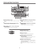
Parts and their functions Front panel controls POWER X /Y Pb / Pr ON 1 2 OFF Z ASPECT 3 Mod i f y H EDITOR V HOLD ON SCENE CENTER GRABBER PATTERN 9 8 7 6 5 4 5 CENTER button 1 POWER switch This is used to switch the AC power on and off.
Parts and their functions Mod i f y 1 2 3 PATTERN REV 8 LUM ONE WAY DSK EFFECTS CHRM EXT P in P 4 7 MIX 5 6 1 REV (reverse) button 6 MIX button This button is used to reverse the keys and transition key patterns, reverse the frame in/out, and reverse the chroma key, luminance key, external key and title α key signals. The button’s lamp flashes with patterns that have no reverse operations, indicating that these patterns cannot be reversed. This is used to call mix transitions.
Parts and their functions 1 2 5 7 9 ; A PROG DSK B PRESET This button forcibly applies the strobe effect to the B/PRESET bus. When the button is pressed, the B/PRESET video effect setting page appears on the LCD screen. The still and strobe field/frame setting is performed using the time effect settings of [Video Effects].
Parts and their functions Setting panel area 2 5 1 POS. 3 X 119 X 107 Z 235 EVENT 4 8 9 Mod i f y ; Pattern Edge Pattern MET ime INT 7 00 02:00 2101 Wht E DR F 6 T r a n s i t i o n : Hard Light On Effects Off = CONTRAST < DSK FADE @ SET UP INT VIDEO AUDIO EFFECTS B C D E > 1 LCD (liquid crystal) display ? A 9 Rotary control setting position display area The effect parameters, time settings and other information are shown on this display.
Parts and their functions 2 5 1 POS. 3 X 119 X 107 Z 235 EVENT 4 8 9 Mod i f y ; Pattern Edge Pattern MET ime INT 7 00 02:00 2101 Wht E DR F 6 T r a n s i t i o n : Hard Light On Effects Off = CONTRAST < DSK FADE ? A @ SET UP INT VIDEO AUDIO EFFECTS B C D E > DR D DSK FADE (DSK/fade setting page display) button A LCD CONTRAST control This control is used to adjust the contrast of the LCD display. This button displays the DSK/fade setting page.
Parts and their functions DR 2 1 PHONE MIN These keys can be used to input numerical values for the event numbers when the event recall button or event setting button is ON, for the pattern numbers when the event recall button or event setting button is OFF and the pattern number setting button is ON, and for the transition times when the pattern number setting button is OFF. TIME 4 MAX PATTERN 7 Number keys 1 to 9 ME 3 DSK FADE 7 8 9 8 4 5 6 9 3 7 1 2 TITLE PLAY INT PLAY 0 .
Parts and their functions 1 2 4 6 8 : < = MIX EFFECTS A / PROG SHIFT SOURCE 1 / 5 SOURCE 2 / 6 SOURCE 3 / 7 FADE SOURCE 4 / 8 INT/EXT AUTO TAKE DSK > ? B / PRESET 1 3 5 7 9 ; 1 SHIFT key 9 B/PRESET / SOURCE 4/8 selector button This key has the same function as the shift key for the number keys. This button is used to select source 4 selected by the initial settings for the B/PRESET bus. When it is pressed together with the shift key, source 8 is selected.
Parts and their functions Audio mixer area SOURCE 1 / 5 SOURCE 2 / 6 SOURCE 3 / 7 SOURCE 4 / 8 MIC / AUX 2 AUX 1 MAX MASTER MAX MIN MIN 1 2 3 4 1 SOURCE 1/5 fader 5 6 7 4 SOURCE 4/8 fader This fader is used to adjust the audio level of input 1 which was set on the initial setting page; when it is operated together with the shift key, it is used to adjust the audio level of input 5.
Parts and their functions Rear panel connection area 1 2 3 4 KEY Y EXT IN P B 5 6 7 8 9 5 8 9 : SDI P R IN1 IN2 IN3 IN4 OUT G/L 1 MIC PHONE USB ADV-REF PREVIEW AUX IN 2 AUDIO OUT 2 L L R R GPI EDITOR EXT IN (external key input area) 1 2 3 4 6 7 1 External key input connector 1 MIC input connector This connector can be used for key or DSK applications. It can also be used for genlock signal using the settings on the initial setting page.
Parts and their functions 1 2 3 4 5 6 7 VIDEO IN Y/V Y/V P /V5 B P R YC Y/V P /V7 B P R YC 8 P /V6 B P R YC P /V8 B P R YC 2 1 Y/V 3 4 AUDIO IN 9 : ; < = > ? @ 1 Composite/component Y input 1 connector 9 Composite/component Y input 3 connector 2 Composite 5/component PB input 1 connector : Composite 7/component PB input 3 connector 3 Component PR input 1 connector ; Component PR input 3 connector 4 YC input 1 connector < YC input 3 connector 5 Composite/component Y input 2 c
Parts and their functions L L R AUDIO IN L R 2 1 1 L R R 4 3 3 2 1 Analog audio 1 input connectors AUDIO OUT 1 R L 4 5 4 Analog audio 4 input connectors The audio signals supplied to these connectors are input to the cross point selected on the initial setting page. The audio signals supplied to these connectors are input to the cross point selected on the initial setting page.
External interfaces This unit comes with three connectors to support four external interfaces: a GPI input connector, RS-422A/RS-232 (9-pin) connector and a Tally output connector. Select the connector that suits the editing controller model used. ∫ RS-232C This enables the unit to be controlled using a personal computer. All of the unit’s functions with the exception of AUX 1 and AUX 2 can be set.
System Diagram By connecting cameras, VTRs and other video components, this unit can digitally process the video signals of these components.
System Diagram Example 3 Editing application RS-422A Editing controller SDI (Audio/Video) Through connection Through connection VTR RS-422A Through connection VTR SDI (Audio/Video) ADV REF *1 G/L *2 (Genlock enabled as genlock source) Signal generator RS-422A SDI IN1 SDI IN2 SDI IN3 Through connection Termination AG-MX70 SDI (Audio/Video) Video camera RS-422A SDI IN4 SDI OUT SDI (Audio/Video) AUX1/AUX2 USB VTR Video camera Analog audio signals CD player, etc.
Power supply and backup The operation panel settings are stored in the memory when the power is turned off. The default settings are established when the power is turned back on by selecting [Power] > [Reset] on the [Setup] initial setting screen, and the system is started from the settings which were established at the completion of the previous session by selecting [Power] > [Preset]. If [Demo] has been selected on the [Setup] panel, the demonstration mode is established when the power is turned on.
[INTVideo] internal video setting screen When [Back Matte] has been selected The joystick XY and rotary Z control displays are set to Wash, and the wash color that is the companion color for gradation is set. The joystick [X][Y] and rotary [Z] display change to [Pb], [Pr] and [Y], and the color can be set. [Pb][Pr] can be set to any value from 0 to 255 and [Y] to any value from 16 to 255 but only when [Custom1] or [Custom2] has been selected using rotary 2 control.
[INTVideo] internal video setting screen When [Memory] has been selected It is possible to write Prog output images in the memory using [Still] (still picture) or [Movie] (moving picture), and then play the written images back. It is possible to set the number of frames (number of pages) that can be used to a maximum of 30 (NTSC) or 26 (PAL). However, if pages are allocated to titles, the number of pages will be reduced by the equivalent amount.
[Color Effects] setting screen Color Effect Pb 128 Pr 128 C Gain 0 Event ME Time 00E Pattern 10:00F 3015 Color Effects Y Setup ch Y Gain 0 R1 INT Pb A Pr 0 R2 Blue C Gain 128 128 R3 R4 0 R5 This menu is selected using the A or B bus [Color Effects] button. If the status of the [Color Effects] button is not to be changed, press the [Color Effects] button of the bus to be set while holding down the [Shift] key. Settings can be performed separately for the A bus and B bus.
[Video Effects] setting screen Pos. X 128 Y 128 Z 128 Event ME Time 00E Pattern 10:00F 3015 INT Blue Video Effects ch Channel display A Size Mosaic Off Defocus XY 0 Level Off 0 Mono Off Time Effects Screen Off Decay Field Paint Scrolled display Level Y 4 C Off H Off V Off 3D Off Level Ripple R1 10F 16 Off Mirror 1 Time Off Nega Time R2 Time 0 Width 16 R3 R4 1 R5 This menu is selected using the A or B bus [Video Effects] button.
[Video Effects] setting screen [Mosaic] setting R1 Select [On] or [Off] for this effect using the rotary 2 control. The default setting is [Off]. Select [XY] (both horizontal and vertical), [X] (horizontal only) or [Y] (vertical only) using the rotary 3 control. Set the size using the rotary 4 control. Any setting from 0 to 30 can be set for Size, and the setting can be changed in 2step increments. The default setting is 8.
[Video Effects] setting screen [Time Effects] still/strobe setting R1 Select the still or strobe effect with Video Effects ON using the rotary 2 control. Time Effects R2 R3 R1 R2 Time Effects R1 ≥ When [Still] has been selected Either [Field] or [Frame] is selected as the type using the rotary 3 control. The default setting is [Field]. Time Effects R5 Screen Still Off Still Strobe ≥ When [Off] has been selected The regular screen is output.
[Video Effects] setting screen [Decay] setting The A and B multi strobe, transition, Key, DSK shadow and trail cannot be selected at the same time. Only one of these effects is valid at a time. Select [On] or [Off] for the effect using the rotary 2 control. Any time setting from 0 to 32 can be selected using the rotary 3 control. The default setting is 16. This level setting is used for the level of transition number 1066 (219).
[Video Effects] setting screen [3D] setting R1 Select [OFF], [Ripple], [Multi] or [Spark] for 3D using the rotary 2 control. This setting is only effective when the 3D optional board (AG-VE70) has been installed. It cannot be made to take effect at the same time as 3D transition or key pattern. The default setting is [Off].
[Video Effects] setting screen ≥ In the case of pattern numbers 200 to 211, 1001 to 1034, 213 to 220, 222, 1060 to 1067 and 1069, transitions can be initiated with the DVE setting parameters applied to the B channel. When this is done, the pattern is changed to MIX (56). (With the A bus/B bus) With the preset bus/program bus, the effects are applied to preset, and they are turned off by setting the reverse button to ON.
Execution of Effects AB transition 3) Pattern selection Select the pattern using the direct transition button or using the number keys. Patterns with numbers 3000 and up are key patterns. Perform the border, shadow, trail and other settings on the LCD setting screen. The separate border, trail and other settings are stored in each direct button and read out. 1) Preparation Slide the transition lever to the A side.
Effect-by-effect setting screens The settings for the transition and key patterns are performed on these screens. The items that can be set differ from one pattern to another. The LCD display changes as soon as one of the patterns is selected. The key slice, slope, key level, crop, edge, effects and DVEPlus settings are stored in the memory for each effect group. If the system was started using Reset, the default settings are established.
Effect-by-effect setting screens [Pattern Edge] setting R1 This is used to set edges for the patterns. The border color set here is used as the border matte for trail. It is updated by the color which is read out for the direct pattern. Select [Hard], [Soft], [Border] or [Soft Border] using the rotary 2 control. The default setting is [Hard]. When [Soft] or [Soft Border] has been selected, No.2001 to 2195 and 6008 to 6010 patterns cannot be selected. When [Soft Border] has been selected, the #701 to No.
Effect-by-effect setting screens [Effects] setting R1 This is used to perform the DVE settings. Select the [Off], [Shadow] or [Trail] effect using the rotary 2 control. Set the [Light] (lighting) using the rotary 5 control. This is valid only when the 3D optional board (AG-VE70) has been installed for use. R2 R3 R4 R5 Effects Light Off On Lights when 3D board has been installed.
Effect-by-effect setting screens [Chroma Key] setting The chroma key is opened directly or when selected using the number keys. ME is automatically selected for the Preview output, and the chroma key cursor and keyed output are displayed. Pos. X 128 Y 128 Z 196 Event ME Time 00E Pattern Display of selected number: 1, 2 or 3 is selected.
Effect-by-effect setting screens [Color cancel] setting This is used to perform the settings for color cancel. The offset from the [Offset] key can be set to any value from 0 to 255 using the rotary 2 control. The [C Slice] (cancel slice) can be set to any value from 0 to 255 using the rotary 3 control. The [C-Area] (cancel area) can be set to any value from 0 to 3 using the rotary 4 control. The [Mono L] (monochrome level) can be set to any value from 0 to 15 using the rotary 5 control.
Effect-by-effect setting screens [Luminance Key] and [EXT Key] (external key) settings The luminance key and external key are opened directly or when selected using the number keys. Pos.
Effect-by-effect setting screens [Title Key] setting The title key is opened directly or when selected using the number keys. It is not displayed when Page is 0. The number of frames (number of pages) that can be stored in the memory for PC Title can be set on the [Setup] screen. Pos.
Effect-by-effect setting screens [Basic Pattern Key] setting (numbers 3001 to 3046) The basic pattern key is opened directly or when selected using the number keys. Pos.
Effect-by-effect setting screens Other key settings (numbers 3301 and up) The pattern keys are opened directly or when selected using the number keys. The size is set using the rotary Z control. With patterns whose positions can be changed, the position can be set using the joystick.
Effect-by-effect setting screens [3Dmodify] setting This takes effect only for the special 3D patterns (numbers 6001 to 6438 and 6601 to 6716) when the 3D optional board (AGVE70) has been installed. The parameters of the pattern for the 3D keys can be changed using the rotary 2, 3, 4 and 5 controls. They can be stored in the memory for each pattern.
Effect-by-effect setting screens R1 ≥ With the page turn group (number 6008) R2 R3 R4 R5 3D Rotate Angle Turn Modify 128 32 R2: [Rotate] (rotation) setting R3: [Angle] setting R4: [Turn] setting R5: [Radius] setting 0 - 255 ≥ With the ripple group (number 6031) R1 R2 0 - 255 Radius 64 0 - 255 R3 0 - 255 0-7 R4 R5 3D Level Time Width Modify 32 64 R2: [Level] (amplitude) setting R3: [Time] setting R4: [Width] setting The position of the ripple center can be changed using [Shift] + XY.
Effect-by-effect setting screens [Key Learn] setting R1 This is used to set key learn. It cannot be set for number 3001 to 3006, 3301 to 3305, 6001 to 6003 and 6006 to 6010 doors. The key XYZ, key level and 3D modify settings are stored in the memory for each key frame. The key patterns are selected using the rotary 2 and 3 controls. Selection is made from 9000 to 9019. [Saved] is displayed for a pattern once set by the pattern number, and [Empty] is displayed for a pattern which has not yet been set.
Effect-by-effect setting screens Pos. X 128 Y 128 Z 196 Event 00E ME Time Pattern INT 10:00F 3013 Wht Key Learn 9000 Insert Replace Basic CLR KF Copy K Frame 00 K Level 255 Paste Exit R1 R2 R3 R4 R5 In the key learn editing mode, the key frame number is displayed in [K Frame]. Using the rotary 1 control, the editing items are selected and key frames are set. Key frames 00 to 19 can be set, and they are displayed during editing in the rotary 2 control display area.
Effect-by-effect setting screens With page turn (#6008) With flag (#6002) R1 R2 R3 R4 R5 R1 Insert Flag CLR KF K Frame 00 Paste Exit R3 R4 R5 Insert Replace Copy R2 K Level 255 Width Angle Time Amp 192 64 48 Replace Page Turn CLR KF K Frame 00 Copy Paste 32 Exit K Level 255 Rotate Angle Turn 128 32 Radius 64 3 R2: [Width] (flag width) setting R3: [Angle] setting R4: [Time] (fluttering time) setting R5: [Amp] (amplitude) setting 3D parameters are the same as with 3DModify.
Effect-by-effect setting screens When a compression effect has been applied to images, some of the effects may be automatically canceled. ≥ When applying 2D compression effects to channel A Under the conditions below, the Still, Strobe and Multi Strobe for channel A are turned OFF when the Transition lever or key size adjustment Z has been changed or the compression rate has been changed by the aspect ratio.
DSK/Fade settings These settings are opened when the DSK/FADE button or DSK Preview is selected. Both DSK and Fade settings can be performed. Select the [DSK Source], [DSK Key], [Crop], [DSK On/Off], [DSK Effects] or [Fade] item using the rotary 1 control. When the title memory is 0, the Key [Memory], Source [Memory], [Memory], [Mode] and [Slide] settings are canceled. Pos.
DSK/Fade settings [DSK Key] settings R1 These are used to set the DSK key signals (for external applications). Memory keys are used in their original form. The [Slice] level can be set to any value from 0 to 255 using the rotary 2 control. The default setting is 0. [Slope] can be set to any value from 0 to 15 using the rotary 3 control. The default setting is 0. The [K Level] (key level) can be set to any value from 0 to 255 using the rotary 5 control. The default setting is 255.
DSK/Fade settings [Fade] settings R1 These are used to perform the fade settings. The image to be faded is selected from [Black], [White] or [Blue] using the rotary 2 control. The default setting is [Black]. [On] or [Off] is selected for [Audio] fading using the rotary 3 control. The default setting is [On]. [After] or [Pre] is selected for [Phone] fading using the rotary 4 control.
[Audio Effects] settings Pos. X 128 Y 128 Z 196 Event ME Time 00E Pattern INT 10:00F 3015 Wht Audio Effects 1-8 Aux1 Aux2 Pan IN Ch Balance Off 1 EQ L Low High On EQ M Level Mid 0 Voice Change 0 0 0 Freq Q 1.01KHz Pitch 0.5 Level Off Up Off AB 5 Mute R1 R2 R3 R4 R5 [Audio Effects] is opened using Audio Effects or the ON button. Audio effects can be set for each input.
[Audio Effects] settings [EQ] equalizer setting R1 This is used to set the equalizers. Set [On] or [Off] for all equalizers using the rotary 3 control. The default setting is [On]. The [L Level] bass level can be set in 2 dB intervals to any value from –14 dB to 0 to +14 dB using the rotary 5 control. The default setting is [0]. The [H Level] treble level can be set in 2 dB intervals to any value from –14 dB to 0 to +14 dB using the rotary 4 control. The default setting is [0].
[Setup] initial setting screen Wash Pb 128 Pr 128 Y 196 Event 00E ME Time Pattern INT 10:00F 3015 Wht Setup Power Reset Direct Pattern Setup Audio Input Video Setup Memory INT V Title 15 Gen Ref In Lock Video Format System1 G/L Scrolled display 15 H Phase SC Phase 128 512 Aspect NTSC Setup 4:3 Dly Time GPI 1Frame Sec System2 Lcd Stby Bus Type ME VBClean DR 0 Off Still RS422 GVG Chr.
[Setup] initial setting screen [Power] (power ON) setting R1 R2 R3 R4 R5 Whether the system is to be started from the [Reset] status, Power from the [Preset] status or in the [Demo] mode can be Reset selected using the rotary 2 control. With [Reset], the settings except for the event memories, Reset setup settings, file memory and key learn settings are Preset initialized.
[Setup] initial setting screen The LCD display now shows the setting screens for each effect pattern. Proceed to set the edges and effects, and if the settings are acceptable, enter them using [Enter], and return to the direct pattern settings. Example of transition Pos.
[Setup] initial setting screen [Audio Video Input] settings These are used to set the audio and video inputs. When [Setup] is selected using the rotary 2 control and [Enter] is pressed, [OK?] appears so press [Enter] to change to the setting mode. Use [Shift] + [Enter] to cancel. When [Default] is selected using the rotary 2 control and [Enter] is pressed, [OK?] appears so press [Enter] to change to the default setting.
[Setup] initial setting screen [Memory] setting R1 This is used to set the memories used for INTVideo and DSK. When the setting is changed, all the memories are cleared. How much memory is to be used for [INT V] and how much for [Title] for DSK and TitleKey is set using the rotary 2 and 3 controls. If the allocation to one memory is changed, the allocation to the other memory will change so that the total remains 30. When a change is to be made, [OK?] appears.
[Setup] initial setting screen [System1] setting R1 R2 R3 R4 R5 This is used to perform a variety of settings. System1 Dly Time GPI RS422 The rotary 2 control is used to set the amount of delay for 1Frame Sec ME GVG the source input when the [AdvRef] advanced reference signal is connected with the 3D optional board (AG-VE70) ME 1Frame Sec GVG installed. If 0Frame is selected, the video delay amount is DSK 0Frame Frame SONY different between when the 3D effects are applied and when Fade they are not.
[Setup] initial setting screen [Audio Level] setting R1 The [Alignment] (alignment) level is set using the rotary 2 control. [–3 dB], [0 dB] or [4 dB] can be selected. The default setting is [4 dB] for NTSC and [0 dB] for PAL. The [Head] (headroom) is set using the rotary 5 control. Either [18 dB] or [20 dB] can be selected. The default setting is [20 dB] for NTSC and [18 dB] for PAL.
Other settings Event memory Setting method Event 00E One hundred panel statuses can be stored in event memories 0 to 99. Press the Set button, set the event number using the number keys, and enter the setting using [Enter]. Set button: Its lamp lights during the setting process. When [Enter] is pressed, it flashes for two seconds and then goes off. When the setting is in progress, Event is displayed in reverse video, and the event is then entered using [Enter].
Other settings Transition time setting Select the item to be set, and press the [ME], [DSK] or [FADE] button. Input the numerical value using the number keys, and press [Enter]. The numerical value can be incremented and decremented using rotary TIME or the “+” and “–” keys. Set the ME (back, key transition), DSK or Mod i f yfade time. Set the time of the item selected for ME, DSK or Fade above the number keys. The time is indicated on the LCD display. It can also be input or output using the number keys.
Transition patterns Basic 1 2 3 4 5 6 7 8 9 10 11 63 64 65 66 67 68 69 70 79 80 81 82 83 84 85 86 87 88 89 303 304 305 306 307 323 324 325 326 343 344 345 346 363 364 365 366 381 382 383 384 385 105 398 106 399 107 400 108 401 109 402 416 417 418 419 429 430 431 432 Pair Blinds Multi H3 301 302 308 Multi V3 321 322 327 328 Multi H6 Overlap 103 341 342 347 348 Multi V6 104 361 362 367 368 Multi HV3 Multi HV6 Multi PairH3 Ov
Transition patterns Basic 12 13 14 15 16 17 18 19 20 21 22 23 71 72 73 74 75 76 77 78 Pair Blinds 90 91 92 93 94 95 96 97 98 100 101 102 309 310 311 312 313 314 315 316 317 318 319 320 329 330 331 332 333 334 335 336 337 338 339 340 349 350 351 352 353 354 355 356 357 358 359 360 369 370 371 372 373 374 375 376 377 378 379 380 386 387 388 389 390 391 392 393 394 395 396 397 110 403 111 404 112 405 113 406 114
Transition patterns Multi PairH6 441 442 443 444 445 455 456 457 458 467 468 469 470 479 480 481 482 Multi PairV6 454 Multi PairHV3 Multi PairHV6 Mtrix 24 701 25 702 26 703 27 704 705 706 707 Overlap 183 801 184 802 185 803 186 804 187 805 188 806 189 807 190 808 191 809 192 810 DVE BPreset Mosaic XY Mosaic X HV Mirror Nega YC Nega Y Nega C Mono Paint Overlap 200 1001 201 1002 202 1003 203 1004 207 1030 208 1031 209 1032 210 1033 211 1034 Shutter STI
Transition patterns Multi PairH6 446 447 448 449 450 451 452 453 459 460 461 462 463 464 465 466 471 472 473 474 475 476 477 478 483 484 485 486 487 488 489 490 LUM CUT MIX SAT MIX 197 1082 198 1083 199 1084 Multi PairV6 Multi HV3 Multi PairHV6 Panel Panel Setting Panel Setting 0 99 Basic2 DVE BPreset Direct Pattern 193 811 194 812 195 813 196 814 CUT Still Field Still Fram Strobe 4Multi Strob 9Multi Strob 16Multi Strob Decay Video aB Fa Color aB
Transition patterns Slide1 Overlap +Diss 43 1301 1311 44 1302 1312 45 1303 1313 46 1304 1314 51 1305 1315 52 1306 1316 53 1307 1317 54 1308 1318 47 1341 48 1342 49 1343 50 1344 134 1345 135 1346 136 1347 137 1348 143 1401 1411 144 1402 1412 145 1403 1413 146 1404 1414 147 1405 1415 148 1406 1416 149 1407 1417 150 1408 1418 151 1421 1431 152 1422 1432 153 1423 1433 154 1424 1434 155 1425 1435 156 1426 1436 157 1427 1437 158 1428 1438 167 1461 1471 168 1462 1472 169 1463 147
Transition patterns Bounce Overlap +Diss 138 1321 1331 139 322 1332 140 1323 1333 159 1441 1451 160 1442 1452 161 1443 1453 162 1444 1454 163 1445 1455 164 1446 1456 165 1447 1457 166 1448 1458 175 1481 1491 176 1482 1492 177 1483 1493 178 1484 1494 179 1485 1495 180 1486 1496 181 1487 1497 182 1488 1498 1631 1671 1632 1672 1633 1673 1634 1674 1635 1675 1636 1676 1637 1677 1638 1678 1651 1691 1652 1692 1653 1693 1654 1694 1655 1695 1656 1696 1657 1697 1658 1698 1734 1754
Transition patterns Spin +Diss 1841 1851 1842 1852 1843 1853 1844 1854 1845 1855 1902 1903 1904 1905 1906 2001 2011 2002 2012 2003 2013 2004 2014 2005 2015 2051 2071 2052 2072 2053 2073 2054 2074 2101 2151 2102 2152 2103 2153 2118 2168 2119 2169 2131 2183 1846 1856 Flip Tumble Overlap 1960 1961 1962 1963 2006 2016 2007 2017 2008 2018 2009 2019 2055 2075 2056 2076 2057 2077 2058 2078 2104 2154 2105 2155 2106 2156 2107 2157 2108 2158 2120 2170 2121 2171 2122 217
Transition patterns Spin 2DComp +Diss 1861 1871 1862 1872 1863 1873 1864 1874 1964 1965 1966 1967 1865 1875 1866 1876 1881 1891 1882 1892 1883 1893 3D DVE Ripple Spark Multi Move 1981 1982 1983 1884 1894 Flip Tumble Overlap Shutter Overlap 1971 1972 1973 1974 2059 2079 2060 2080 2061 2081 2062 2082 2063 2083 2064 2084 2065 2085 2066 2086 2067 2087 2109 2159 2110 2160 2111 2161 2112 2162 2113 2163 2114 2164 2115 2165 2116 2166 2117 2167 2126 2176 2127 2177 2128
Key patterns BasicPattern Key Diss Exp Exp+Diss 3001 3021 3041 3002 3022 3042 3003 3023 3043 3004 3024 3044 3005 3025 3045 3006 3026 3046 Basic Key CHR LUM EXT Overlap 62 3101 61 3102 59 3103 3301 3311 3321 3302 3312 3322 3303 3313 3323 3304 3314 3324 3401 3411 3402 3412 3403 3413 3404 3414 3405 3415 3406 3416 3407 3417 3408 3418 3441 3451 3442 3452 3443 3453 3444 3454 3445 3455 3446 3456 3447 3457 3448 3458 3501 3511 3502 3512 3503 3513 3504 3514 3505 3515 3516 3516
Key patterns Spot Light Back Diss Exp Exp+Diss 3305 Back 3315 3325 2D Move Exp +Diss 3421 3431 3422 3432 3423 3433 3424 3434 3425 3435 3426 3436 3427 3437 3428 3438 3461 3471 3462 3472 3463 3473 3464 3474 3465 3475 3466 3476 3467 3477 3468 3478 3521 3531 3522 3532 3523 3533 3524 3534 3525 3535 3526 3536 3527 3537 3528 3538 3561 3571 3562 3572 3563 3573 3564 3574 3565 3575 3566 3576 3567 3577 3568 3578 4631 4671 4632 4672 4633 4673 4634 4674 4635 4675 4636 4676 4
Key patterns Pers1 2DComp +Diss 4701 4741 4702 4742 4703 4743 4704 4744 4705 4745 4706 4746 4707 4747 4708 4748 4730 4750 4731 4751 4732 4752 4733 4753 4761 4781 4762 4782 4763 4783 4764 4784 4765 4785 4766 4786 4767 4787 4768 4788 4801 4821 4802 4822 4803 4823 4804 4824 4805 4825 4806 4826 4807 4827 4808 4828 4841 4851 4842 4852 4843 4853 4844 4854 4845 4855 4846 4856 5201 5231 5202 5232 5203 5233 5204 5234 5205 5235 5206 5236 5207 5237 5208 5238 5209 5239 5401 5
Key patterns Pers1 2DComp +Diss 4734 4754 4735 4755 4736 4756 4737 4757 4738 4758 4739 4759 4769 4789 4770 4790 4771 4791 4772 4792 4773 4793 4861 4871 4862 4872 4863 4873 4864 4874 4865 4875 4866 4876 4881 4891 4882 4892 4883 4893 4884 4894 5210 5240 5211 5241 5212 5242 5213 5243 5214 5244 5215 5245 5216 5246 5217 5247 5218 5248 5219 5249 5220 5250 5413 5473 5414 5474 5415 5475 5416 5476 5417 5477 5418 5478 5419 5479 5420 5480 5421 5481 5422 5482 5423 5483 5441 5
Key patterns Accordion Move +Diss 6201 6211 6202 6212 6203 6213 6204 6214 6205 6215 6206 6216 6207 6217 6208 6218 6301 6311 6302 6312 6303 6313 6304 6314 6305 6315 6306 6316 6307 6317 6308 6318 6401 6411 6402 6412 6403 6413 6404 6414 6405 6415 6406 6416 6407 6417 6408 6418 6501 6521 6502 6522 6503 6523 6504 6524 6505 6525 6506 6526 6507 6527 6508 6528 6601 6611 6602 6612 6603 6613 6604 6614 6605 6615 6606 6616 6607 6617 6608 6618 Move +Diss 6701 6711 6702 6712 670
Key patterns Accordion Move +Diss 6221 6231 6222 6232 6223 6233 6224 6234 6225 6235 6226 6236 6227 6237 6228 6238 6229 6239 6321 6331 6322 6332 6323 6333 6324 6334 6325 6335 6326 6336 6327 6337 6328 6338 6329 6339 6421 6431 6422 6432 6423 6433 6424 6434 6425 6435 6426 6436 6427 6437 6428 6438 6621 6631 6622 6632 6623 6633 6624 6634 Sphere Move +Diss Sphere Curve Move +Diss Pers In Move +Diss Title Key Key Key Key Key Key Key Key Key Key Learn11 Learn12 Learn13 Learn14 Learn
About this software Description of the software System requirements The software contained in the CD is described below. The PC to be used should meet the following requirements. ∫ USB driver This driver software is for communications when the AGMX70 is connected to a PC via the USB port.
Processing of image data ≥ ROLL Two or more images are lined up one after the other and played back (scrolled) vertically on the screen. It is possible to set the direction and the speed for scrolling. Only Title data can be used with this method. It is possible to set the horizontal position of the image. ∫ By data type Image data is processed by the AG-MX70 either as Title data or IntVideo data, depending on the application.
Processing of image data ∫ Management of the image memory ≥ Memory capacity Images transmitted from the PC are stored in the AG-MX70’s image memory. The memory capacity differs, depending on the AG-MX70’s video format setting. NTSC: 30 pages (1 page = amount of memory required for 1 image on Monitor 1 screen) PAL: 26 pages The image memory is divided into separate areas for Title data and IntVideo data and capacity can be allocated freely as required.
Before use AG-MX70 connections 6) Select “Search for the best driver for your device,” then click on the “Next” button. It is necessary to connect the PC to the AG-MX70 using the USB cable before installing the software. Follow the steps below. 1) Turn off the power to the AG-MX70. 2) Connect the PC to the AG-MX70 using the USB cable. Insert the USB cable connectors into the corresponding USB ports on the PC and on the rear panel of the AG-MX70. This completes the connection.
Before use ∫ For Windows XP Be sure to log on as a user with Administrator rights when installing this software. ∫ For Windows ME 1) Connect the PC to the AG-MX70 correctly. 2) Turn on the power to the PC. Check that Windows has started up. 1) Connect the PC to the AG-MX70 correctly. 3) Place the setup CD-ROM in the PC’s CD-ROM drive. 2) Turn on the power to the PC. Check that Windows has started up. 4) Turn on the power to the AG-MX70.
Before use Installation of MX-Navi 5) The installation contents confirmation screen appears. To proceed with the installation of the contents shown, click the “Next” button. To change the contents, use the “Back” button to return to the previous screen, and change the settings. After installing the USB driver, install MX-Navi, the software for handling image exchange with the AG-MX70. Follow the steps below. 1) Select “Run…” from the “Start” menu. Click the “Browse” button, select Setup.
Startup and shutdown How to start up MX-Navi Select “Program” > “Panasonic AG-MX70” > “MX-Navi” from the Windows Start menu. How to shut down MX-Navi Shutdown is possible in the following two ways. ≥ Click the button at the right top of the main window. ≥ Select “Exit” from the “File” menu of the main window. Screen descriptions Main window A list of Title data, called the transmission list, is displayed on the main window. The main window of MX-Navi has two display modes, the icon mode and the list mode.
Screen descriptions 4 D, F 8 OFF The upper line shows the Divide value for the data and the lower line shows the number of images of the data. The operation at the time of DSK OFF will be displayed. The display contents are the same as for DSK ON. When double-clicked, the Properties window (page 86) will open. 5 ICON The image is reduced and displayed. When several files are used with one title, one of them will be used for the display.
Screen descriptions List mode 3 4 5 6 7 8 9 1 2 1 For data with a Mark setting, the Mark number is 7 TYPE displayed. The data playback format will be displayed. When double-clicked, the Properties window (page 86) will open. 2 This is displayed for data with the Protect setting. Data playback format 3 O (Order) The order of the data in the transmission list is displayed. This is the same as with icon mode. Duration (This appears only when Auto Trigger of DSK OFF is valid.
Menu descriptions File menu Write Flash memory This writes the data of the saved file into the flash memory of the AG-MX70. Select this menu item after turning on the power while holding down the “0” key and “5” key on the operation panel of the AG-MX70 and setting the AG-MX70 to the flash memory backup mode. A dialog box now appears so select the file and click the “OK” button to write the file data. When this operation is performed, all the data in the flash memory of the AG-MX70 is replaced.
Menu descriptions Cursor menu Delete This deletes the selected title from the transmission list. The same operation can be performed with the “DEL” key or by right-clicking on the title data display column and selecting “Delete” from the pop-up menu. Top This moves the cursor to the start of the transmission list. The same operation can be performed with the operation button or with the HOME key. Select all This selects all titles in the transmission list.
Menu descriptions Operation menu Tool menu (effective only when the AG-MX70 is connected) Memory status This displays the memory status screen. For details, refer to “Checking the memory status of the AG-MX70” (page 90). AutoLoad This automatically transmits the data from the selected data to the end of the list and performs DSK playback. For details, refer to “Automatic transmission and playback of Title data” (page 88).
Title data operations Flow until Title data playback Setting the Title data playback properties The procedure for transmission of PC images as Title data and DSK playback is as follows. Setting of special effects with DSK ON, DSK OFF, the data display position, etc. will be done automatically according to the initial value settings at the time the data was registered in the transmission list. These settings can be changed on the Properties screen of the data.
Title data operations Off: This is used for setting the operation to be performed when the data is deleted from the screen (DSK OFF). ≥ AutoTrigger: This sets the start operation. No check: DSK OFF will be performed when the playback button on the main window is pressed or when the DSK button on the main unit is pressed. Check: DSK OFF will be performed according to the time set for Duration. ≥ Effect: ≥ Slide : Same as for DSK ON. Same as for DSK ON.
Title data operations Manual transmission and playback of Title data Automatic transmission and playback of Title data The data from the cursor position to the end of the transmission list can be transmitted automatically and DSK playback can be performed automatically. Select “Operation” > “Autoload” from the menu of the main window. Data registered in the transmission list can be transmitted to the AG-MX70 using the following procedure.
Title data operations Checking the Title data image Reordering the transmission list The image of the data selected on the image display screen can be displayed in the original size so it can be checked. The image display screen can be displayed using one of the following methods. The transmission list can be reordered by any one of the following methods. ≥ Select the reordering method as “Sort by name” or “Sort by comments” from the “Display” menu.
Other operations Checking the memory status of the AG-MX70 Changing the AG-MX-70 memory settings The status of the image memory of the AG-MX70 can be checked on the memory status screen. Select “Tools” > “Memory status” from the menu of the main window to open the memory status screen. The settings of the AG-MX70 (switching between NTSC and PAL, switching between 4:3 and 16:9, changing the page distribution between Title data and IntVideo data) can be changed from the PC.
Other operations Transmission and playback of IntVideo data Saving data The operations for transmission and playback of PC images as IntVideo data is described below. Title data or IntVideo data can be read to the PC from the image memory of the AG-MX70 and can be stored as still images. Use the following procedure. 1) Select “Tools” > “Memory status” from the menu of the main window and open the memory status screen.
Other operations Setting the initial properties The initial values for the properties to be used with new data can be set on the “Initial set of Property Data” setting screen. 1) Select “Initial set of Property Data” from the Tools menu of the main window. The “Initial set of Property Data” setting screen is displayed. 2) Set the individual items and click the “OK” button to change the settings. All settings can be returned to the initial value by pressing the “Cancel” button.
Other operations Setting the operating environment 3 File Management The operation settings for this application can be set on the operation environment screen. When adding an image that has once been used as title data to the transmission list, select whether the previous property settings are to be used. The previous properties can be cleared using the “Clear previous property” button. 1) Select “Operating environment” from the Tools menu of the main window. The Environment screen will be displayed.
List of short-cut keys Move the cursor to the top Home Move the cursor back by 10 Move the cursor back Select all the data Ctrl + A Left arrow Delete the selected data Delete Up arrow Cut out the selected data Ctrl + X Move the cursor ahead Down arrow Copy the selected data Ctrl + C Move the cursor ahead by 10 Right arrow Paste the data Ctrl + V Clear the selected data Ctrl + R Clear all data Ctrl + T Move the cursor to the bottom Jump to the data in DSK End 0 Jump to the data of the
Before calling for service Troubleshooting Contact your dealer if the problem persists even when you have checked the following items. AG-MX70-related problems Problem What to check ≥ The power can not be ≥ Is the plug of the power cable inserted properly in the outlet? ≥ Has the fan stopped operating? switched on. ≥ There is no picture.
Before calling for service MX-Navi-related problems Problem What to check ≥ Patterns set for DSK ON When the set pattern can not be used for DSK, the pattern is changed automatically to a and DSK OFF for Title different pattern. data are changed. ≥ The Title data has been When Protect has been set for the data, it will not be cleared even when clearing is performed cleared, but the data has from the menu of the main window.
Specifications [GENERAL] Power Source : 120 V AC, 50/60 Hz Power Consumption : 52 W (with no optional accessories installed), 70 W (with all optional accessories installed) indicates safety information. Operating temperature: Operating humidity: Dimensions (W k H k D): Weight: 41 °F to 104 °F (+ 5 °C to + 40 °C) Less than 90% (relative humidity) 16-3/4 k 7-3/4 k 15-3/4 inch (424 k 197 k 400 mm) 8.2 kg (with no optional accessories installed) 8.
Specifications [VIDEO INPUT/OUTPUT] Component input connectors: Composite input connectors: YC input connectors: EXT (external input) connector: G/L input connector: Component output connectors: Composite output connectors: YC input connectors: Preview output connector: Advanced reference input connector: BNC a 4 (sources 1/2/3/4) Y: 1.0 Vp-p, 75 h Pb/Pr (525): 0.525/0.757 Vp-p switchable, 75 h Pb/Pr (625): 0.7 Vp-p, 75 h BNC a 8 (sources 1 to 8), 1.0 Vp-p, 75 h Mini-DIN4 a 4 (sources 1/2/3/4) Y: 1.
Specifications [OTHER] Editor: Connectable Editor: Tally Out: GPI: USB: D-sub 9-pin, RS-422A/232C switchable RS-422A protocol; GVG/Sony switchable Panasonic: AG-A850, AJ-A900, SONY: BVE-2000, BVE-910, PVE-500 D-sub 9-pin, open-collector k 8 ch Collector current: Less than 50 mA, Maximum voltage: 35 V DC BNC k 1, Make-contact Type-B connector k 1, USB Ver.1.1 (cable length: max.
PANASONIC BROADCAST & TELEVISION SYSTEMS COMPANY UNIT COMPANY OF MATSUSHITA ELECTRIC CORPORATION OF AMERICA Executive Office: One Panasonic Way 4E-7, Secaucus, NJ 07094 (201) 348-7000 EASTERN ZONE: One Panasonic Way 4E-7, Secaucus, NJ 07094 (201) 348-7621 Southeast Region: 1225 Northbrook Parkway, Ste 1-160, Suwanee, GA 30024 (770) 338-6835 Central Region: 1707 N Randall Road E1-C-1, Elgin, IL 60123 (847) 468-5200 WESTERN ZONE: 3330 Cahuenga Blvd W.