TECHNICAL & SERVICE MANUAL INDOOR UNIT : CS-MKE7NKU CS-MKE9NKU CS-MKE12NKU CS-MKE18NKU CS-MKE24NKU DC INVERTER MULTI-SYSTEM AIR CONDITIONER Capacity Indoor Model No. Product Code No.
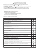
SAFETY PRECAUTIONS • Before doing repair work, please read the " SAFETY PRECAUTIONS" carefully and fully understand them. • The precautionary items here are divided into " Warning" and " Caution" items. Items in particular which may cause death or serious injury to the service personnel if the work is not performed correctly, are included in the " Warning" table. However, even precautionary items identified as " Caution" also have the potential for serious consequences if not performed correctly.
Warning If refrigerant gas blows off during the work, do not touch the refrigerant gas as it may cause frostbite. Prohibit If refrigerant gas leaks during the work, ventilate the room. If refrigerant gas catches fire, harmful gas may be generated. Do not mix any gas other than the specified refrigerant gas in the refrigerating cycle. If air or other contaminants mix with the gas, pressure will become extremely high in the refrigerating cycle, which may cause a unit breakdown.
Table of Contents Page SAFETY PRECAUTIONS ............................................................................................................. 2 TABLE OF CONTENTS .................................................................................................................... 4 ................................................................................... 5 1. OPERATING RANGE ..............................................................................................................
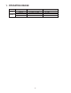
APPLICABLE MULTI-OUTDOOR UNITS Multi-Outdoor Unit 3-Room 4-Room 4-Room CU-3KE19NBU CU-4KE24NBU CU-4KE31NBU CS-MKE7NKU YES YES YES CS-MKE9NKU YES YES YES CS-MKE12NKU YES YES YES CS-MKE18NKU YES YES YES CS-MKE24NKU NO YES YES Indoor Unit 5
1. OPERATING RANGE Temperature Cooling Heating Indoor Air Intake Temp. Outdoor Air Intake Temp.
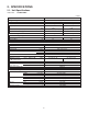
2. SPECIFICATIONS 2-1.
Indoor Unit CS-MKE7NKU < 208V > Type Wall Mounted Type Indoor Unit 208V Single-Phase 60Hz Voltage Rating Performance Capacity Air Circulation (Hi/Me/Lo) Moisture Removal (High) Electrical Rating Available Voltage Range Running Amperes Power Input Features Control / Temperature Control Control Unit Timer Fan Speeds Airflow Direction (Indoor) BTU/h kW ft3/min (m3/h) Pints/h Package Dimensions Weight Shipping Volume Height Width Depth Height Width Depth Net Shipping Heating 8,500 2.
Indoor Unit CS-MKE9NKU < 230V > Type Wall Mounted Type Indoor Unit Voltage Rating 230V Single-Phase 60Hz Performance Capacity Air Circulation (Hi/Me/Lo) Moisture Removal (High) Electrical Rating Available Voltage Range Running Amperes Power Input Features Control / Temperature Control Control Unit Timer Fan Speeds Airflow Direction (Indoor) BTU/h kW ft3/min (m3/h) Pints/h Package Dimensions Weight Shipping Volume Height Width Depth Height Width Depth Net Shipping Heating 12,200 3.
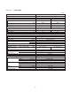
Indoor Unit CS-MKE9NKU < 208V > Type Wall Mounted Type Indoor Unit Voltage Rating 208V Single-Phase 60Hz Performance Capacity Air Circulation (Hi/Me/Lo) Moisture Removal (High) Electrical Rating Available Voltage Range Running Amperes Power Input Features Control / Temperature Control Control Unit Timer Fan Speeds Airflow Direction (Indoor) BTU/h kW ft3/min (m3/h) Pints/h Cooling 9,000 2.65 259(440) / 241(410) / 212(360) 3.4 Heating 12,200 3.
Indoor Unit CS-MKE12NKU < 230V > Type Wall Mounted Type Indoor Unit Voltage Rating 230V Single-Phase 60Hz Performance Capacity Air Circulation (Hi/Me/Lo) Moisture Removal (High) Electrical Rating Available Voltage Range Running Amperes Power Input Features Control / Temperature Control Control Unit Timer Fan Speeds Airflow Direction (Indoor) BTU/h kW ft3/min (m3/h) Pints/h Cooling 11,900 3.50 282(479) / 259(440) / 218(370) 4.26 Heating 14,300 4.
Indoor Unit CS-MKE12NKU < 208V > Type Wall Mounted Type Indoor Unit Voltage Rating 208V Single-Phase 60Hz Performance Capacity Air Circulation (Hi/Me/Lo) Moisture Removal (High) Electrical Rating Available Voltage Range Running Amperes Power Input Features Control / Temperature Control Control Unit Timer Fan Speeds Airflow Direction (Indoor) BTU/h kW ft3/min (m3/h) Pints/h Cooling 11,900 3.50 282(479) / 259(440) / 218(370) 4.26 Heating 14,300 4.
Indoor Unit CS-MKE18NKU < 230V > Type Wall Mounted Type Indoor Unit 230V Single-Phase 60Hz Voltage Rating Performance Capacity Air Circulation (Hi/Me/Lo) Moisture Removal (High) Electrical Rating Available Voltage Range Running Amperes Power Input Features Control / Temperature Control Control Unit Timer Fan Speeds Airflow Direction (Indoor) BTU/h kW ft3/min (m3/h) Pints/h Cooling 17,500 5.15 500(850) / 447(760) / 377(641) 4.89 Heating 20,400 6.
Indoor Unit CS-MKE18NKU < 208V > Type Wall Mounted Type Indoor Unit 208V Single-Phase 60Hz Voltage Rating Performance Capacity Air Circulation (Hi/Me/Lo) Moisture Removal (High) Electrical Rating Available Voltage Range Running Amperes Power Input Features Control / Temperature Control Control Unit Timer Fan Speeds Airflow Direction (Indoor) BTU/h kW ft3/min (m3/h) Pints/h Cooling 17,500 5.15 500(850) / 447(760) / 377(641) 4.89 Heating 20,400 6.
Indoor Unit CS-MKE24NKU < 230V > Type Wall Mounted Type Indoor Unit 230V Single-Phase 60Hz Voltage Rating Performance Capacity Air Circulation (Hi/Me/Lo) Moisture Removal (High) Electrical Rating Available Voltage Range Running Amperes Power Input Features Control / Temperature Control Control Unit Timer Fan Speeds Airflow Direction (Indoor) BTU/h kW ft3/min (m3/h) Pints/h Cooling 24,200 7.10 541(919) / 500(850) / 435(739) 4.89 Heating 29,000 8.
Indoor Unit CS-MKE24NKU < 208V > Type Wall Mounted Type Indoor Unit 208V Single-Phase 60Hz Voltage Rating Performance Capacity Air Circulation (Hi/Me/Lo) Moisture Removal (High) Electrical Rating Available Voltage Range Running Amperes Power Input Features Control / Temperature Control Control Unit Timer Fan Speeds Airflow Direction (Indoor) BTU/h kW ft3/min (m3/h) Pints/h Cooling 24,200 7.10 541(919) / 500(850) / 435(739) 4.89 Heating 29,000 8.
2-2. Major Component Specifications 2-2-1. Indoor Unit Indoor Unit CS-MKE7NKU Control PCB Part No. Controls Control Circuit Fuse CB-CS-MKE7NKU Microprocessor 250V 3A Fan Type Q'ty ... Dia. and Length Cross-Flow 1 ... D3-5/8 / L24-31/32 (D92/L634) inch (mm) Fan Motor Type Model ... Q'ty No. of Poles Rough Measure RPM (Cool / Heat) Nominal Output Coil Resistance (Ambient Temp.
Indoor Unit CS-MKE9NKU Control PCB Part No. Controls Control Circuit Fuse CB-CS-MKE9NKU Microprocessor 250V 3A Fan Type Q'ty ... Dia. and Length Cross-Flow 1 ... D3-5/8 / L24-31/32 (D92/L634) inch (mm) Fan Motor Type Model ... Q'ty No. of Poles Rough Measure RPM (Cool / Heat) Nominal Output Coil Resistance (Ambient Temp. 68 °F (20 °C)) Safety Device Type Over-Current Protection Over-Heat Protection Run Capacitor Flap Motor Type Model Rating Coil Resistance (Ambient Temp.
Indoor Unit CS-MKE12NKU Control PCB Part No. Controls Control Circuit Fuse CB-CS-MKE12NKU Microprocessor 250V 3A Fan Type Q'ty ... Dia. and Length Cross-Flow 1 ... D3-5/8 / L24-31/32 (D92/L634) inch (mm) Fan Motor Type Model ... Q'ty No. of Poles Rough Measure RPM (Cool / Heat) Nominal Output Coil Resistance (Ambient Temp. 68 °F (20 °C)) Safety Device Type Over-Current Protection Over-Heat Protection Run Capacitor Flap Motor Type Model Rating Coil Resistance (Ambient Temp.
Indoor Unit CS-MKE18NKU Control PCB Part No. Controls Control Circuit Fuse CB-CS-MKE18NKU Microprocessor 250V 3A Fan Type Q'ty ... Dia. and Length Cross-Flow 1 ... D3-5/8 / L33-9/32 (D92/L845) inch (mm) Fan Motor Type Model ... Q'ty No. of Poles Rough Measure RPM (Cool / Heat) Nominal Output Coil Resistance (Ambient Temp. 68 °F (20 °C)) Safety Device Type Over-Current Protection Over-Heat Protection Run Capacitor Flap Motor Type Model Rating Coil Resistance (Ambient Temp.
Indoor Unit CS-MKE24NKU Control PCB Part No. Controls Control Circuit Fuse CB-CS-MKE24NKU Microprocessor 250V 3A Fan Type Q'ty ... Dia. and Length Cross-Flow 1 ... D3-5/8 / L33-9/32 (D92/L845) inch (mm) Fan Motor Type Model ... Q'ty No. of Poles Rough Measure RPM (Cool / Heat) Nominal Output Coil Resistance (Ambient Temp. 68 °F (20 °C)) Safety Device Type Over-Current Protection Over-Heat Protection Run Capacitor Flap Motor Type Model Rating Coil Resistance (Ambient Temp.
2-3. Other Component Specifications Model No. of sensor Sensor Name PTM-D51HS4-1 TH2 PTM-D51HS4-2 TH2 Indoor air temp sensor Quantity of Sensor CS-MKE7NKU CS-MKE9NKU CS-MKE12NKU CS-MKE18NKU CS-MKE24NKU 1 1 1 0 0 0 0 0 1 1 10 Resistance (k ohm) 9 8 7 6 5 4 3 2 1 0 50 59 68 77 86 95 104 (10) (15) (20) (25) (30) (35) (40) Temperature °F (°C) Model No.
3.
Indoor Unit CS-MKE18NKU CS-MKE24NKU Unit: inch(mm) (852-0-0010-216-00-0) 24
4. REFRIGERANT FLOW DIAGRAM 4-1. Refrigerant Flow Diagram Indoor Unit CS-MKE7NKU CS-MKE9NKU CS-MKE12NKU Indoor unit O.D. 3/8" (9.52 mm) Indoor heat exchanger O.D. 1/4" (6.35 mm) Cooling cycle Heating cycle Indoor Unit CS-MKE18NKU Indoor unit O.D. 1/2" (12.7 mm) Indoor heat exchanger O.D. 1/4" (6.35 mm) Cooling cycle Heating cycle Indoor Unit CS-MKE24NKU Indoor unit O.D. 5/8" (15.88 mm) Indoor heat exchanger O.D. 1/4" (6.
5. PERFORMANCE DATA 5-1. Air Throw Distance Charts Indoor Unit Cooling CS-MKE7NKU Room air temp.:80°F (26.7°C) Fan speed:High Horizontal distance (ft.) 0 5 10 15 20 25 30 25 30 Axis air velocity (ft./sec.) Vertical distance (ft.) 0 5 10 15 : Flap angle 0° , : Flap angle 30° , Heating : Axis air velocity 0° : Axis air velocity 30° Room air temp.:70°F (21.1°C) Fan speed:High Horizontal distance (ft.) 0 5 10 15 20 Axis air velocity (ft./sec.) Vertical distance (ft.
Indoor Unit Cooling CS-MKE9NKU Room air temp.:80°F (26.7°C) Fan speed:High Horizontal distance (ft.) 0 5 10 15 20 25 30 25 30 Axis air velocity (ft./sec.) Vertical distance (ft.) 0 5 10 15 : Flap angle 0° , : Flap angle 30° , Heating : Axis air velocity 0° : Axis air velocity 30° Room air temp.:70°F (21.1°C) Fan speed:High Horizontal distance (ft.) 0 5 10 15 20 Axis air velocity (ft./sec.) Vertical distance (ft.
Indoor Unit Cooling CS-MKE12NKU Room air temp.:80°F (26.7°C) Fan speed:High Horizontal distance (ft.) 0 5 10 15 20 25 30 25 30 Axis air velocity (ft./sec.) Vertical distance (ft.) 0 5 10 15 : Flap angle 0° , : Flap angle 30° , Heating : Axis air velocity 0° : Axis air velocity 30° Room air temp.:70°F (21.1°C) Fan speed:High Horizontal distance (ft.) 0 5 10 15 20 Axis air velocity (ft./sec.) Vertical distance (ft.
Indoor Unit Cooling CS-MKE18NKU Room air temp.:80°F (26.7°C) Fan speed:High Horizontal distance (ft.) 0 5 10 15 20 25 30 25 30 Axis air velocity (ft./sec.) Vertical distance (ft.) 0 5 10 15 : Flap angle 0° , : Flap angle 30° , Heating : Axis air velocity 0° : Axis air velocity 30° Room air temp.:70°F (21.1°C) Fan speed:High Horizontal distance (ft.) 0 5 10 15 20 Axis air velocity (ft./sec.) Vertical distance (ft.
Indoor Unit Cooling CS-MKE24NKU Room air temp.:80°F (26.7°C) Fan speed:High Horizontal distance (ft.) 0 5 10 15 20 25 30 25 30 Axis air velocity (ft./sec.) Vertical distance (ft.) 0 5 10 15 : Flap angle 0° , : Flap angle 30° , Heating : Axis air velocity 0° : Axis air velocity 30° Room air temp.:70°F (21.1°C) Fan speed:High Horizontal distance (ft.) 0 5 10 15 20 Axis air velocity (ft./sec.) Vertical distance (ft.
6. ELECTRICAL DATA 6-1.
7. FUNCTIONS 7-1. Operation Functions Emergency operation SENSOR DRY Emergency operation is available when the remote controller malfunctions, has been lost, or otherwise cannot be used. During DRY operation, the system adjusts the room temperature and fan speed according to the conditions in the room, in order to maintain a comfortable room environment. To operate the system, press the OPERATION button, which is also used as the receiver, below the unit display.
HIGH POWER NIGHT SETBACK This function acts to raise the power but keeps the AC system in the same operating mode. This function is set with the HIGH POWER button on the remote controller. (It can be set regardless of the temperature and fan speed settings.) When NIGHT SETBACK operation is set, the temperature and fan speed settings will be adjusted automatically to allow comfortable sleep. When NIGHT SETBACK operation is set, " mark" appears on the remote controller.
7-2. Protective Functions Overload prevention during heating Cold-air prevention during heating Indoor heat exchanger temperature °F(°C) During HEAT operation, the temperature of the indoor heat exchanger is used to control the frequency and lessen the load on the compressor before the protective device is activated. Indoor heat exchanger A. Control start B. Control end A T1 During heating, the fan speed is set to "LL" (very low) or stopped.
8. TROUBLESHOOTING (BEFORE CALLING FOR SERVICE) 8-1. Precautions before Performing Inspection or Repair After checking the self-diagnostics monitor, turn the power OFF before starting inspection or repair. High-capacity electrolytic capacitors are used inside the outdoor unit controller (inverter). They retain an electrical charge (charging voltage DC 310V) even after the power is turned OFF, and some time is required for the charge to dissipate.
(1) Self-diagnostics Lamps INDOOR UNIT (1) OPERATION lamp (2) TIMER lamp (3) QUIET lamp OPERATION button REMOTE CONTROL receiver Since the indications cover various units, the corresponding parts listed below may not be present in some models. .... OFF INDICATION ON INDOOR UNIT QUIET (3) TIMER (2) OPERATION (1) CODE S01 S02 S03 S04 S05 DIAGNOSIS CONTENTS POSSIBLE MALFUNCTION COMPRESSOR TEMP.
(2) If the self-diagnostics function fails to operate Check the indoor unit. No indicators illuminate and the indoor fan does not rotate. Check the power voltage. Blown Is the fuse blown? Normal Replace the circuit board or the fuse. Replace the controller.
8-3. Checking the Indoor and Outdoor Units (1) Checking the indoor unit No. 1 Control Use the remote controller to operate the unit in "TEST run" mode. To determine whether the mode is currently in "TEST run" mode, check the 4 indicator lamps on the unit. If all 4 are blinking, the current mode is "TEST run." Check items (unit operation) • The rated voltage must be present between inter-unit wirings 1 and 2. • Connect a 5 k ohm resistor between inter-unit wirings 2 and 3.
(3) How to Identify a Serial Communication Error If the lamps on the main body show the following conditions after the completion of self-diagnosis, a communication error between the indoor unit and outdoor unit might be considered. In such a case, identify the breakdown section by using the following procedure. NOTE Refer to "Method of Self-Diagnosis" for the self-diagnosis procedure.
(3-2) Condition: E12 1. Disconnect the inter-unit wiring on the indoor unit side. 2. Operate the system in TEST RUN mode. Then, five minutes later, perform the self-diagnosis. Condition: E01 What is the self-diagnosis result ? Condition: E12 1. Disconnect the inter-unit wiring on the outdoor unit side. 2. Operate the system in TEST RUN mode. Then, five minutes later, perform the self-diagnosis. An error in the P. C. Board in the indoor unit might be considered. (Terminal board error, etc.
8-4. Trouble Diagnosis of Fan Motor 8-4-1. Indoor Fan Motor This indoor DC fan motor contains an internal control PCB. Therefore, it is not possible to measure the coil resistance, and the following procedure should be used to check the motor. To perform diagnosis, operate the unit in cooling mode with indoor fan speed "High". Next, make sure that the indoor unit receive the signals from the remote controller when the ON/OFF operation button is pressed.
8-5. Noise Malfunction and Electromagnetic Interference An inverter A/C operates using pulse signal control and high frequencies. Therefore, it is susceptible to the effects of external noise, and is likely to cause electromagnetic interference with nearby wireless devices. A noise filter is installed for ordinary use, preventing these problems. However, depending on the installation conditions, these effects may still occur. Please pay attention to the points listed below.
APPENDIX A Operating Instructions CS-MKE7NKU CS-MKE9NKU CS-MKE12NKU (852-6-4181-217-00-2) A-1
Operating Instructions Split System Air Conditioner Model No. Indoor Units Outdoor Units CS-MKE7NKU CS-MKE9NKU CS-MKE12NKU CU-3KE19NBU CU-4KE24NBU CU-4KE31NBU This air conditioner uses the refrigerant R410A. Before operating the unit, read these operating instructions thoroughly and keep them for future reference.
FEATURES This air conditioner is an inverter type unit that automatically adjusts capability as appropriate. Details on these functions are provided below; refer to these descriptions when using the air conditioner. • Microprocessor Controlled Operation The interior compartment of the remote controller contains several features to facilitate automatic operation, easy logically displayed for easy use.
INSTALLATION LOCATION • We recommend that this air conditioner be installed properly by qualified installation technicians in accordance with the Installation Instructions provided with the unit. Before installation, check that the voltage of the electric supply in your home or office is the same as the voltage shown on the nameplate. • • • Avoid: Do not install this air conditioner where there are fumes or flammable gases, or in an extremely humid space such as a greenhouse.
• • • • • • CAUTION • • • • • • • • NOTICE 4 To prevent possible hazards from insulation failure, the unit must be grounded. Do not clean inside the indoor and outdoor units by users. Engage authorized dealer or specialist for cleaning. In case of malfunction of this appliance, do not repair by yourself. Contact to the sales dealer or service dealer for a repair. Refrigerant gas leakage may cause fire. For safety, be sure to turn the air conditioner off and also to disconnect the power before cleaning.
NAMES OF PARTS Air Intakes INDOOR UNIT Air Outlet Remote Controller Drain Hose Refrigerant Tubes OUTDOOR UNIT Air Outlet NOTE This illustration is based on the external view of a standard model. Consequently, the shape may differ from that of the air conditioner which you have selected. This air conditioner consists of an indoor unit and an outdoor unit. You can control the air conditioner with the remote controller.
UNIT DISPLAY AND OPERATION BUTTON INDOOR UNIT IMPORTANT Avoid using radio equipment such as mobile phone near (within 4 ft. (1.2m)) the remote control receiver. Some radio equipment may cause malfunction of the unit. QUIET OPERATION button If the trouble happens, disconnect power and restart the air conditioner after a few minutes.
REMOTE CONTROLLER (DISPLAY) Displayed when transmitting data Displayed when indoor unit sensor is in use Displayed when setting temperature Displayed when temperature is shown Displayed when setting timer Displayed when the time display is set to 12-hour time. Symbols (1) Operation mode AUTO ......................................... HEAT .......................................... MILD DRY .................................. COOL .........................................
REMOTE CONTROLLER Transmitter Sensor (Cover closed) Display QUIET button ON/OFF operation button 1 HR. TIMER button Temperature setting buttons (TEMP.
REMOTE CONTROLLER (CONTINUED) MODE selector button Use this button to select AUTO, HEAT, DRY or COOL mode. (AUTO) : The air conditioner calculates the difference between the thermostat setting and room temperature, and automatically selects ‘‘COOL’’ or ‘‘HEAT’’ mode as appropriate. (HEAT) : The air conditioner makes the room warmer. (DRY) (COOL) NOTE FAN SPEED selector button : The air conditioner reduces the humidity in the room. : The air conditioner makes the room cooler.
REMOTE CONTROLLER (CONTINUED) Temperature Display Selector button This switches the temperature display between °C and °F. Time Display Selector button This switches the time display between 24-hour time and 12-hour time. ACL button (ALL CLEAR) ADDRESS switch Puts the remote controller into pre-operation status. Always press this button after replacing the batteries.
USING THE REMOTE CONTROLLER (CONTINUED) How to Use the Remote Controller When using the remote controller, always point the unit’s transmitter head directly at the air conditioner’s receiver. Air Conditioner (Indoor unit) Receiver (Transmitter head) Remote Controller Remote Controller Installation Position The remote controller may be operated either from a non-fixed position or from a wall-mounted position.
OPERATION WITH THE REMOTE CONTROLLER 1. Automatic Operation The air conditioner calculates the difference between the thermostat setting and room temperature, and automatically determines the mode to operate under cooling or heating. Then, the air conditioner continuously operates under the mode selected at initial operation. STEP 2 STEP 1 NOTE Check that the circuit breaker on the power panel is turned on.
OPERATION WITH THE REMOTE CONTROLLER (CONTINUED) 2. Manual Operation STEP 2 STEP 3 STEP 1 STEP 4 STEP 5 NOTE Check that the circuit breaker on the power panel is turned on. If the automatic operation settings of the unit do not meet your needs, press the setting buttons as described below and change the settings as desired. STEP 1 Press the MODE selector button and select the desired mode.
OPERATION WITH THE REMOTE CONTROLLER (CONTINUED) NOTE • Choose the best position in the room for the remote controller, which also acts as the sensor for room comfort and transmits the operating instructions. Once you’ve found this best position, always keep the remote controller there. • This appliance has a built-in 5-minute time delay circuit to ensure reliable operation. When the operation button is pressed, the compressor will start running within three minutes.
OPERATION WITH THE REMOTE CONTROLLER (CONTINUED) 4. Night Setback Mode Night Setback Mode is used for saving energy. Press the NIGHT SETBACK button while unit is operating. The mark appears in the display. To release the night setback function, press the NIGHT SETBACK button again. NOTE Pressing the MODE selector button cancels Night Setback mode. A.
OPERATION WITH THE REMOTE CONTROLLER (CONTINUED) 5. QUIET Mode QUIET Mode is used to reduce the fan sound of the indoor unit. Press the QUIET button. The mark appears in the display. To cancel, press QUIET button again. • • In QUIET Mode, the fan rotates at a slower speed than the fan speed setting. If the unit is already operating with a very low airflow, the fan sound may not change even if the QUIET button is pressed. 6.
SPECIAL REMARKS ‘‘DRY’’ ( ) Operation How it works? • • • Heating ( Once the room temperature reaches the level that was set, the unit’s operation frequency is changed automatically. During DRY operation, the fan speed automatically runs at lower speed for providing a comfortable breeze. ‘‘DRY’’ operation is not possible if the indoor temperature is 59 °F or less.
SETTING THE TIMER NOTE 1. How to set the present time In the descriptions below, the following settings are used for the temperature and time indicator selector button on the bottom front section of the remote controller. • Temperature: °F • Time: AM, PM (Example) To set to 10:30 pm. Operation 2. How to set the OFF time 1. Press the CLOCK button once if the time indicator is not flashing. The time indication alone flashes. 2. Press the Advance, Return ( , ) button until PM 10:30 is displayed.
SETTING THE TIMER (CONTINUED) 3. How to set the ON time (Example) To start operation at 7:10 am. Operation 4. How to set DAILY ON/OFF REPEAT timer Indication 1. Press the ON TIME setting button once. The timer indication is displayed, and the present ON time is shown. 2. Press the Advance, Return ( , ) button until AM 7:10 is displayed. The timer indication blinks. The time can be set in 10-minute increments. Holding down the button advances the time rapidly in 10-minute increments. 3.
USING THE 1-HOUR OFF TIMER 1. 1-Hour OFF Timer This function causes the unit to operate for one hour and then stop, regardless of whether the unit is on or off when this button is pressed. The indicator in the display indicates that this function is operating. Setting procedure: Regardless of whether the unit is operating or stopped, press the 1 HR. TIMER button. appears in the display.
ADJUSTING THE AIRFLOW DIRECTION 1. Horizontal The horizontal airflow can be adjusted by moving the vertical vanes with your hands to the left or right. When the humidity is high, the vertical vanes should be in the front position during the cooling or dehumidifying operation. If the vertical vanes are positioned all of the way to the right or left, condensation may begin to form around the air vent and drip down. CAUTION 2.
OPERATION WITHOUT THE REMOTE CONTROLLER INDOOR UNIT If you have lost the remote controller or it has trouble, follow the steps below. When the air conditioner is not running Each time the OPERATION button is pressed, the type of operation conducted is indicated by the changing color of the OPERATION lamp. Press the button and select the lamp color that suits your preference for operation.
CARE AND CLEANING (CONTINUED) Filter How to remove the filter The filter behind the air intake grille should be checked and cleaned at least once every two weeks. 1. Grasp both ends of the air intake grille, and remove it by opening towards the front and pulling towards you. Air intake grille 2. Remove the filter attached to the rear of the air intake grille. Cleaning How to replace the filter filter Use a vacuum cleaner to remove light dust.
CARE AND CLEANING (CONTINUED) Cleaning the main unit and Remote Controller • • • Removing and remounting the air intake grille CAUTION Washing the grille with water Wipe clean using a soft, dry cloth. To remove stubborn dirt, moisten a cloth in warm water no hotter than 104 °F, wring thoroughly, and then wipe. The air intake grille can be removed in order to wash it with water. Refer to “How to remove the filter” and “How to replace the filter” on page 23.
TROUBLESHOOTING (BEFORE CALLING FOR SERVICE) If your air conditioner does not work properly, first check the following points before requesting service. If it still does not work properly, contact your dealer or service center. Trouble Air conditioner does not run at all. Possible Cause Remedy 1. Power failure. 1. Restore power. 2. Leakage circuit breaker tripped. 2. Contact service center. 3. Line voltage is too low. 3. Consult your electrician or dealer. 4.
SPECIFICATIONS Indoor Unit CS-MKE9NKU CS-MKE12NKU Power Source Single-phase, 208-230 V, 60 Hz 2.20 2.65 3.50 kW Cooling Capacity 7,500 9,000 11,900 BTU/h kW 2.50 3.60 4.
APPENDIX B Operating Instructions CS-MKE18NKU CS-MKE24NKU (852-6-4181-218-00-2) A-2
Operating Instructions Split System Air Conditioner Model No. Indoor Units Outdoor Units CS-MKE18NKU CS-MKE24NKU CU-3KE19NBU CU-4KE24NBU CU-4KE31NBU This air conditioner uses the refrigerant R410A. Before operating the unit, read these operating instructions thoroughly and keep them for future reference.
FEATURES This air conditioner is an inverter type unit that automatically adjusts capability as appropriate. Details on these functions are provided below; refer to these descriptions when using the air conditioner. • Microprocessor Controlled Operation The interior compartment of the remote controller contains several features to facilitate automatic operation, easy logically displayed for easy use.
INSTALLATION LOCATION • We recommend that this air conditioner be installed properly by qualified installation technicians in accordance with the Installation Instructions provided with the unit. Before installation, check that the voltage of the electric supply in your home or office is the same as the voltage shown on the nameplate. • • • Avoid: Do not install this air conditioner where there are fumes or flammable gases, or in an extremely humid space such as a greenhouse.
• • • • • • CAUTION • • • • • • • • NOTICE 4 To prevent possible hazards from insulation failure, the unit must be grounded. Do not clean inside the indoor and outdoor units by users. Engage authorized dealer or specialist for cleaning. In case of malfunction of this appliance, do not repair by yourself. Contact to the sales dealer or service dealer for a repair. Refrigerant gas leakage may cause fire. For safety, be sure to turn the air conditioner off and also to disconnect the power before cleaning.
NAMES OF PARTS Air Intakes INDOOR UNIT Air Outlet Remote Controller Drain Hose Refrigerant Tubes OUTDOOR UNIT Air Outlet NOTE This illustration is based on the external view of a standard model. Consequently, the shape may differ from that of the air conditioner which you have selected. This air conditioner consists of an indoor unit and an outdoor unit. You can control the air conditioner with the remote controller.
UNIT DISPLAY AND OPERATION BUTTON INDOOR UNIT IMPORTANT Avoid using radio equipment such as mobile phone near (within 4 ft. (1.2 m)) the remote control receiver. Some radio equipment may cause malfunction of the unit. QUIET OPERATION button If the trouble happens, disconnect power and restart the air conditioner after a few minutes.
REMOTE CONTROLLER (DISPLAY) Displayed when transmitting data Displayed when indoor unit sensor is in use Displayed when setting temperature Displayed when temperature is shown Displayed when setting timer Displayed when the time display is set to 12-hour time. Symbols (1) Operation mode AUTO ......................................... HEAT .......................................... MILD DRY .................................. COOL .........................................
REMOTE CONTROLLER Sensor Transmitter (Cover closed) Display ON/OFF operation button QUIET button 1 HR. TIMER button Temperature setting buttons (TEMP.
REMOTE CONTROLLER (CONTINUED) MODE selector button Use this button to select AUTO, HEAT, DRY or COOL mode. (AUTO) : The air conditioner calculates the difference between the thermostat setting and room temperature, and automatically selects ‘‘COOL’’ or ‘‘HEAT’’ mode as appropriate. (HEAT) : The air conditioner makes the room warmer. (DRY) (COOL) NOTE FAN SPEED selector button : The air conditioner reduces the humidity in the room. : The air conditioner makes the room cooler.
REMOTE CONTROLLER (CONTINUED) Temperature Display Selector button This switches the temperature display between °C and °F. Time Display Selector button This switches the time display between 24-hour time and 12-hour time. ACL button (ALL CLEAR) ADDRESS switch Puts the remote controller into pre-operation status. Always press this button after replacing the batteries.
USING THE REMOTE CONTROLLER (CONTINUED) How to Use the Remote Controller When using the remote controller, always point the unit’s transmitter head directly at the air conditioner’s receiver. Air Conditioner (Indoor unit) Remote Controller Remote Controller Installation Position The remote controller may be operated either from a non-fixed position or from a wall-mounted position.
OPERATION WITH THE REMOTE CONTROLLER 1. Automatic Operation The air conditioner calculates the difference between the thermostat setting and room temperature, and automatically determines the mode to operate under cooling or heating. Then, the air conditioner continuously operates under the mode selected at initial operation. STEP 2 STEP 1 NOTE Check that the circuit breaker on the power panel is turned on.
OPERATION WITH THE REMOTE CONTROLLER (CONTINUED) 2. Manual Operation STEP 2 STEP 3 STEP 1 STEP 4 STEP 5 NOTE Check that the circuit breaker on the power panel is turned on. If the automatic operation settings of the unit do not meet your needs, press the setting buttons as described below and change the settings as desired. STEP 1 Press the MODE selector button and select the desired mode.
OPERATION WITH THE REMOTE CONTROLLER (CONTINUED) NOTE • Choose the best position in the room for the remote controller, which also acts as the sensor for room comfort and transmits the operating instructions. Once you’ve found this best position, always keep the remote controller there. • This appliance has a built-in 5-minute time delay circuit to ensure reliable operation. When the operation button is pressed, the compressor will start running within three minutes.
OPERATION WITH THE REMOTE CONTROLLER (CONTINUED) 4. Night Setback Mode Night Setback Mode is used for saving energy. Press the NIGHT SETBACK button while unit is operating. The mark appears in the display. To release the night setback function, press the NIGHT SETBACK button again. NOTE Pressing the MODE selector button cancels Night Setback mode. A.
OPERATION WITH THE REMOTE CONTROLLER (CONTINUED) 5. QUIET Mode QUIET Mode is used to reduce the fan sound of the indoor unit. Press the QUIET button. The mark appears in the display. To cancel, press QUIET button again. • • In QUIET Mode, the fan rotates at a slower speed than the fan speed setting. If the unit is already operating with a very low airflow, the fan sound may not change even if the QUIET button is pressed. 6.
SPECIAL REMARKS ‘‘DRY’’ ( ) Operation How it works? • • • Heating ( Once the room temperature reaches the level that was set, the unit’s operation frequency is changed automatically. During DRY operation, the fan speed automatically runs at lower speed for providing a comfortable breeze. ‘‘DRY’’ operation is not possible if the indoor temperature is 59 °F or less.
SETTING THE TIMER NOTE 1. How to set the present time In the descriptions below, the following settings are used for the temperature and time indicator selector button on the bottom front section of the remote controller. • Temperature: °F • Time: AM, PM (Example) To set to 10:30 pm. Operation 2. How to set the OFF time 1. Press the CLOCK button once if the time indicator is not flashing. The time indication alone flashes. 2. Press the Advance, Return ( , ) button until PM 10:30 is displayed.
SETTING THE TIMER (CONTINUED) 3. How to set the ON time (Example) To start operation at 7:10 am. Operation 4. How to set DAILY ON/OFF REPEAT timer Indication 1. Press the ON TIME setting button once. The timer indication is displayed, and the present ON time is shown. 2. Press the Advance, Return ( , ) button until AM 7:10 is displayed. The timer indication blinks. The time can be set in 10-minute increments. Holding down the button advances the time rapidly in 10-minute increments. 3.
USING THE 1-HOUR OFF TIMER 1. 1-Hour OFF Timer This function causes the unit to operate for one hour and then stop, regardless of whether the unit is on or off when this button is pressed. The indicator in the display indicates that this function is operating. Setting procedure: Regardless of whether the unit is operating or stopped, press the 1 HR. TIMER button. appears in the display.
ADJUSTING THE AIRFLOW DIRECTION 1. Horizontal The horizontal airflow can be adjusted by moving the vertical vanes with your hands to the left or right. When the humidity is high, the vertical vanes should be in the front position during the cooling or dehumidifying operation. If the vertical vanes are positioned all of the way to the right or left, condensation may begin to form around the air vent and drip down. CAUTION 2.
OPERATION WITHOUT THE REMOTE CONTROLLER INDOOR UNIT If you have lost the remote controller or it has trouble, follow the steps below. When the air conditioner is not running Each time the OPERATION button is pressed, the type of operation conducted is indicated by the changing color of the OPERATION lamp. Press the button and select the lamp color that suits your preference for operation.
CARE AND CLEANING (CONTINUED) Filter How to remove the filter The filter behind the air intake grille should be checked and cleaned at least once every two weeks. 1. Grasp both ends of the air intake grille, and remove it by opening towards the front and pulling towards you. Air intake grille 2. Remove the filter attached to the rear of the air intake grille. Cleaning How to replace the filter Filter Use a vacuum cleaner to remove light dust.
CARE AND CLEANING (CONTINUED) Cleaning the main unit and remote controller • • • Removing and remounting the air intake grille CAUTION Washing the grille with water Wipe clean using a soft, dry cloth. To remove stubborn dirt, moisten a cloth in warm water no hotter than 104 °F, wring thoroughly, and then wipe. The air intake grille can be removed in order to wash it with water. Refer to “How to remove the filter” and “How to replace the filter” on page 23.
TROUBLESHOOTING (BEFORE CALLING FOR SERVICE) If your air conditioner does not work properly, first check the following points before requesting service. If it still does not work properly, contact your dealer or service center. Trouble Possible Cause Air conditioner does not run at all. Remedy 1. Power failure. 1. Restore power. 2. Leakage circuit breaker tripped. 2. Contact service center. 3. Line voltage is too low. 3. Consult your electrician or dealer. 4.
SPECIFICATIONS Indoor Unit Model No. CS-MKE18NKU Power Source Cooling Capacity Heating Capacity Cooling Operation Operation (H/M/L) Sound Heating Operation (H/M/L) Unit Dimensions (H×W×D) (Indoor unit : Include panel) Net Weight Single-phase, 208-230 V, 60 Hz kW 5.15 7.10 BTU/h 17,500 24,200 kW 6.00 8.50 BTU/h 20,400 29,000 dB(A) 41/38/34 44/41/38 dB(A) 40/37/34 43/40/37 inch (mm) 11-23/32×41-15/16×8-5/8 (298×1,065×219) 11-23/32×41-15/16×8-5/8 (298×1,065×219) lbs. (kg) 26.5 (12.
APPENDIX C INSTALLATION INSTRUCTIONS CS-MKE7NKU CS-MKE9NKU CS-MKE12NKU CS-MKE18NKU CS-MKE24NKU (852-6-4190-583-00-0) A-3
For Indoor Unit INSTALLATION INSTRUCTIONS Split System Air Conditioner Contents This air conditioner uses the refrigerant R410A. NOTE Page External diameter of service port R410A: 5/16" Model Combinations IMPORTANT! Please Read Before Starting .................................. 2 1. GENERAL .......................................................... 4 1-1. Tools Required for Installation (not supplied) 1-2. Accessories Supplied with Unit 1-3. Optional Copper Tubing Kit 1-4.
IMPORTANT! Please Read Before Starting When Transporting Be careful when picking up and moving the indoor and outdoor units. Get a partner to help, and bend your knees when lifting to reduce strain on your back. Sharp edges or thin aluminum fins on the air conditioner can cut your fingers. This air conditioning system meets strict safety and operating standards. As the installer or service person, it is an important part of your job to install or service the system so it operates safely and efficiently.
$SSO\ UHIULJHUDQW OXEULFDQW WR WKH PDWFKLQJ VXUIDFHV RI the flare and union tubes before connecting them, then tighten the nut with a torque wrench for a leak-free connection. &OHDQ XS WKH VLWH DIWHU \RX ILQLVK UHPHPEHULQJ WR FKHFN that no metal scraps or bits of wiring have been left inside the unit being serviced.
1. General 6. 7. 8. 9. 10. 11. 12. 13. 14. 15. This booklet briefly outlines where and how to install the air conditioning system. Please read over the entire set of instructions for the indoor and outdoor units and make sure all accessory parts listed are with the system before beginning. 1-1. Tools Required for Installation (not supplied) 1. Standard screwdriver 2. Phillips head screwdriver 3. Knife or wire stripper 4. Tape measure 5.
1-5. Additional Materials Required for Installation 1. 2. Refrigeration (armored) tape Insulated staples or clamps for connecting wire (See local codes.) Putty Refrigeration lubricant Clamps or saddles to secure refrigerant tubing 3. 4. 5. Indoor unit 2. Installation Site Selection 2-1. Indoor Unit WARNING To prevent abnormal heat generation and the possibility of fire, do not place obstacles, enclosures and grilles in front of or surrounding the air conditioner in a way that may block air flow.
install the indoor unit more than 3.3' (1 m) away from any antenna or power lines or connecting wires used for television, radio, telephone, security system, or intercom. Electrical noise from any of these sources may affect operation. install in a sturdy manner to avoid increased operating noise. Table 3 Model Max. Allowable Tubing Length Per Unit (ft.) Max. Allowable Total Tubing Length at Shipment (L1+L2+L3) or (L1+L2+L3+L4) (ft.) Limit of Total Tubing Length (L1+L2+L3) or (L1+L2+L3+L4) (ft.
3. How to Install the Indoor Unit 3-1. Remove the Rear Panel from the Unit (1) Remove and discard the set screw on the rear panel. (Fig. 6) (2) Press the 2 marks on the frame cover and disengage the stationary tabs from the frame. (Fig. 7) Set screw only for transportation (3) Remove the rear panel. Fig. 6 NOTE Tubing can be extended in 5 or 6 directions as shown in Fig. 8. Select the direction you need providing the shortest run to the outside unit.
(4) Using a sabre saw, key hole saw or hole-cutting drill attachment, cut a hole in the wall. See Table 4 and Fig. 10. NOTE Hole should be made at a slight downward slant to the outdoor side. Table 4 Indoor side Hole Dia. CS-MKE7NKU CS-MKE9NKU CS-MKE12NKU CS-MKE18NKU CS-MKE24NKU 2-9/16" (65 mm) 3-5/32" (80 mm) (5) Measure the thickness of the wall from the inside edge to the outside edge and cut PVC pipe at a slight angle 1/4" (6 mm) shorter than the thickness of the wall. (Fig.
Grille Air intake grille 3-4. Removing and Installing the Grille 3-4-1. Indoor unit types (CS-MKE7NKU, CS-MKE9NKU, CS-MKE12NKU) Basically, these models can be installed and wired without removing the grille. If access to any internal part is needed, follow the steps as given below. CAUTION Fig. 16a Be sure to wear work gloves during installation to avoid being cut by the sharp aluminum fins of the heat exchanger.
3-4-2. Indoor unit types (CS-MKE18NKU, CS-MKE24NKU) Grille Air intake grille Basically, these models can be installed and wired without removing the grille. If access to any internal part is needed, follow the steps as given below. How to remove the grille (1) Grasp both ends of the air intake grille, and remove it by opening towards the front and pulling towards you. (Fig. 16a-1) Fig. 16a-1 (2) Remove the 3 screws. (Fig. 16b-1) (3) Remove the screw on the right side cover plate and open the cover.
3-5. Shape the Indoor Side Tubing (1) Arrangement of tubing by directions Frame a) Right or left tubing Cut out the corner of the right/left frame with a hacksaw or the like. (Figs. 20 and 21) Left tubing outlet b) Right-rear or left-rear tubing In this case, the corner of the frame need not be cut. (2) To mount the indoor unit on the rear panel: Fig. 20 Hang the 2 mounting slots of the unit on the upper tabs of the rear panel. (Fig. 22) Frame 3-6.
3-7. Wiring Instructions for Inter-unit Connections Rear panel (1) Insert the inter-unit wiring (according to local codes) into the through-the-wall PVC pipe. Run the wiring toward the indoor side allowing approx. 10" (25 cm) to extend from the wall face. (Fig. 24) Wall Plastic cover (2) Grasp both ends of the air intake grille, and remove it by opening towards the front and pulling towards you. Wiring 10" (25 cm) (3) Remove the screw on the right side cover plate and open the cover. (Fig. 25) Fig.
WARNING Loose wiring may cause the terminal to overheat or result in unit malfunction. A fire hazard may also exist. Therefore, be sure all wiring is tightly connected. When connecting each power wire to the corresponding terminal, follow the instructions “How to connect wiring to the terminal” and fasten the wire securely tight with the fixing screw of the terminal plate. 9/32" (7 mm) (ACTUAL SIZE) STRIP SIZE How to connect wiring to the terminal a) For Indoor Unit Fig.
3-8. Mounting (1) To install the indoor unit, mount the indoor unit onto the 2 tabs on the upper part of the rear plate. (2) Hold down the air discharge outlet and press the lower part of the indoor unit until it clicks to securely fasten to the 2 tabs on the lower part of the rear plate. (Fig. 33) Push NOTE For tubing, choose either the right or left tubing direction and follow the steps below.
Left-side tubing Rear panel /HDG WKH WXELQJ DQG GUDLQ KRVH WKURXJK WKH ZDOO allowing sufficient length for connection. Then bend the tubing using a tube bender to make the attachment. (Fig. 38) Hole in wall Bent part (2) Switch the drain hose and drain cap. Fig. 38 Switching drain hose and drain cap D Wide tube Narrow tube /RFDWH WKH GUDLQ KRVH DQG WKH GUDLQ FDS )LJ 39) (b) Remove the screw fastening the drain hose on the right side, and pull out the drain hose to remove it. (Fig.
To unmount indoor unit Press the 2 marks on the lower part of the indoor unit and unlatch the tabs. Then lift the indoor unit and unmount. (Fig. 42) 3-9. Drain Hose a) The drain hose should be slanted downward to the outdoors. (Fig. 43) b) Never form a trap in the course of the hose. c) If the drain hose will run in the room, insulate the hose with insulation* so that chilled condensation will not damage furniture or floors. (Fig. 44) Push * Foamed polyethylene or its equivalent is recommended.
4. How to Test Run the Air Conditioner After turning on the power of the air conditioner, use the remote controller and follow the steps below to conduct the test run. (1) Set the remote controller in Test Run mode. (Fig. 59a) a)Press and hold the QUIET button and the 1HR. TIMER button. E 7KHQ SUHVV DQG KROG WKH $&/ 5HVHW EXWWRQ ZLWK D pointed object such as the tip of a pen. After 5 secRQGV UHOHDVH WKH $&/ EXWWRQ ILUVW ON/OFF operation button QUIET button c) Then release the QUIET and 1HR.
5. Remote Controller Installation Position The remote controller can be operated from either a non-fixed position or a wall-mounted position.
6. Address Switch Tab 6-1. Address Setting of the Remote Controller The address can be set in order to prevent interference between remote controllers when 2 indoor units are installed near each other. The address is normally set to “A.” To set a different address, it is necessary to change the address on the second remote controller. Fig. 62 NOTE Once changed, you cannot restore the original address setting of the air conditioner. (1) Switch on the power source.
7. Connecting a Home Automation Device The HA (white) 4P terminal is located on the indoor unit PCB. If a HA device will be used, connect it to this terminal. 8. Installation Check Sheet The strength of the installation location is sufficient to support the air conditioner weight. The indoor and outdoor units are installed level and vertically. The power and voltage are as specified. Inter-unit cables are securely inserted into the terminal block. Inter-unit cables are securely fixed.
DC1111-0