Digital Camera/VTR AJ- P Operating Instructions
For your safety FCC NOTE: This device complies with Part 15 of the FCC Rules. To assure continued compliance follow the attached installation instructions and do not make any unauthorized modifications. CAUTION RISK OF ELECTRIC SHOCK DO NOT OPEN CAUTION: TO REDUCE THE RISK OF ELECTRIC SHOCK, DO NOT REMOVE COVER (OR BACK). NO USER-SERVICEABLE PARTS INSIDE. REFER SERVICING TO QUALIFIED SERVICE PERSONNEL.
Contents Safety Precautions . . . . . . . . . . . . . . . . 2 General and Features . . . . . . . . . . . . . . 5 ÁFeatures of the Camera Section . . . . . 5 ÁFeatures of the VTR Section . . . . . . . 8 ÁSystem Configuration . . . . . . . . . . . . . 9 Controls and Their Functions ÁPower Supply Section . . . . . . . . . . . . . 10 ÁAccessory Mounting Section . . . . . . . 11 ÁAudio Function Section . . . . . . . . . . . . 12 ÁShooting (Recording)/Playback Function Section . . . . . . . . . . . . . . . . .
Contents Adjusting the White Balance/Black Balance ÁAdjusting the White Balance . . . . . . . . 70 ÁAdjusting the Black Balance . . . . . . . . 75 Setting the Electronic Shutter ÁShutter Modes . . . . . . . . . . . . . . . . . . 77 ÁSetting the Shutter Mode/Speed . . . . . 78 ÁSetting the Synchro Scan Mode . . . . . 79 ÁChanging the Shutter Speed/Mode Selection Range . . . . . . . . . . . . . . . . . 80 Changing the Iris Automatic Adjustment Reference Value . . . . . . . . . . . . . . . .
General and Features This unit combines as a single integrated unit a 3-CCD color video camera which features ITCCDs and a 520,000-pixel on-chip lens, and a DVCPRO format VTR which incorporates compression technology. In particular, the screen aspect ratio can be switched between 16:9 and 4:3 in a single action.
Features Automatic adjustment and memory functions for black balance/white balance The black set, black balance and white balance can be automatically adjusted by simple switch operations. Adjustment values are held in the memory even if the power for the unit is turned off, so there is no need to readjust the balance each time the power is turned on.
Features Audio functions ÁA phantom power supply type super-cardioid microphone (option) can be attached and it can also be detached from the main unit for use in interviews. ÁMicrophone can also be connected, and can be attached to the main unit using the AJ-MH700P microphone holder (option). ÁThe audio CH1 recording level can be easily adjusted at the front panel of the unit.
Features Features of the VTR section Digital system The VTR section features a component digital recording system that employs the latest compression technology and non-compressed PCM recording for audio. This system provides superior S/ N, frequency band and waveform characteristics as well as reproduction of detailed areas, etc., and realizes even higher picture and sound quality.
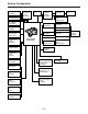
System Configuration Microphone kit AJ-MC700P 1.5½ viewfinder AJ-VF10P/-VF15P Wireless microphone receiver WX-RA700 Shoulder belt 2.
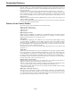
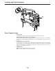
Controls and Their Functions 1 4 2 3 Power Supply Section e Battery holder The battery pack (option) made by Anton Bauer is mounted onto this holder. f DC IN (external power input) connector (XLR, 4P) The AJ-B75 AC adaptor (option) is plugged into this socket when the unit is to be operated by AC power. An external battery is plugged in when an external battery is to be used to operate the unit.
Accessory Mounting Section i Hook for mounting shoulder belt Attach the accessory shoulder belt to this hook. j Light shoe Mount the video light, etc. onto this shoe. k Lens mount (bayonet type) Mount the lens here. l Lens clamping lever Insert the lens into the lens mount k, and turn the lens mount ring using this lever to clamp the lens. m Lens mount cap Press up the lens clamping lever l to remove this cap. Keep the cap in place if the lens is not going to be mounted.
Controls and Their Functions Audio Function Section (1) r AUDIO LEVEL CH1 (audio channel 1 recording level) control When the AUDIO SELECT CH1/CH2 switch u is set to MAN, the recording level of audio channel 1 can be adjusted by this control in addition to the AUDIO LEVEL CH1 control t on the side panel. s MIC IN (microphone input) jack (XLR, 3-pin) Connect an optional microphone to this jack. The power for the microphone is supplied from this jack.
Controls and Their Functions | } ~ t u v w † x ° Audio Function Section (2) { y z | ALARM (warning tone volume) control This adjusts the warning tone volume heard from the speaker ~ or the earphone connected to the PHONES jack ¡. When it is set to the lowest position, the warning tone is not audible. However, by making changes to the inside parts, the tone can be made audible even when the control is at its lowest position.
Controls and Their Functions © ¢ £ § ¶ • (The viewfinder shown in the illustration is the AJ-VF10P.) Shooting (Recording)/Playback Function Section (1) ¢ Viewfinder (optional accessory) Black-and-white images can be seen in the viewfinder during recording and playback. Warnings and messages relating to the unit’s operating status and settings, zebra pattern, markers (safety zone marker, center marker), etc. can also be seen.
Controls and Their Functions ´ ® ™ ß ¨ ≠ (The viewfinder shown in the illustration is the AJ-VF10P.) Æ Shooting (Recording)/Playback Function Section (2) ‹ CC/ND FILTER (filter selector) knob This selects the filter to match the light source which is illuminating the subject. If the setting of this knob is changed when the menu display mode has been set to “3” (default setting), the new setting will appear on the setting change message display area of the viewfinder screen.
Controls and Their Functions ≥ ≤ ± ∞Ø Shooting (Recording)/Playback Function Section (3) fl OUTPUT (output signal selector)/AUTO KNEE switch This switch selects the video signals which are to be output from the camera unit to the VTR unit, viewfinder and video monitor. The AUTO KNEE function can be used when the images shot by the camera have been selected. È OUTPUT/AUTO KNEE switch setting positions BARS Color bar signals are output. The AUTO KNEE circuit is not activated.
Controls and Their Functions µ ∂ ¥ ‡ ECU REMOTE (remote control) connector (6-pin) Connect the AQ-EC1 extension control unit (option) here. |Note{ The POWER switches on unit and extension control unit must be set to OFF before the remote control cable is connected or disconnected. · 26-pin/12-pin output adaptor (See page 104 for mounting method.) The 26-pin/12-pin output adaptor AJ-YA900P (option) is mounted on this section.
Controls and Their Functions Shooting (Recording)/Playback Function Section (4) • VTR START button When this pressed, recording commences; when it is pressed again, recording stops. This button has the same function as the VTR button on the lens side. ‚ VTR SAVE/STBY (tape protection) switch This selects the power supply status while the VTR recording is temporarily stopped (REC PAUSE). SAVE: This is the tape protection mode. The cylinder is stopped in the half-loading status.
… MARK button This is used when the Picture Link (Pix Link)F1 function is to be used. Each time it is pressed M1 (MARK1), M2 (MARK2) or no display appears in the viewfinder. F1Picture Link adaptor board (AJ-YAP900) is sold as an option. ‰ EJECT (cassette eject) button Press this to insert or eject the cassette. ¾ REW (rewind) button Press this to rewind the tape. Its lamp lights during rewinding.
Controls and Their Functions Ã Õ Œ » √ ( ) ( ) ( ) ≈ ∆« ƒ – œœ Menu Operation Section ˆ Setup card insertion slot The optional setup cards are inserted into this slot. ˜ MENU SET/OFF switch This displays the setting menu on the viewfinder screen through VIDEO OUT connector. SET: The page on which the previous setting menu operations were completed appears on the viewfinder screen. (When the menu is used for the first time, the first of the pages which can be displayed appears.
Controls and Their Functions À … ˚ TC IN connector (BNC): The time code serving as the reference is input when the time code is locked to an external source. ¸ TC OUT connector (BNC): Connect this to the time code TC IN connector on the external VTR when locking the external VTR’s time code to this unit’s time code. Time Code-Related Section (2) Ì HOLD button The time data appearing on the counter display at the instant when this button is pressed is held.
Controls and Their Functions ‘ ’ “ ÷ ◊ ÿ — ” (The viewfinder shown in the illustration is the AJ-VF10P.) Ñ TCG (time code selector) switch This is used to set the running mode of the internal time code generator. F-RUN: This position is used when the time code is to be advanced continuously regardless of the VTR’s operation. Set to this position when aligning the time code with the actual time or locking the time code to an external source.
– 23 –
Power Supply Using the Panasonic AU-BP402 Battery Pack 1 Detach the battery mounts. 2 Connect the unit’s connectors with the connectors of the AU-M402H battery case. 3 Mount the AU-M402H battery case. Open the battery case cover and lift up the rubber cap to expose the screw holes. Tighten the screws with a screwdriver and mount the case to the unit. Be sure to tighten the screws completely. |Notes{ ÁDo not pull strongly on the rubber cap.
Power Supply 4 Connect the battery pack plug to the connector inside the case and insert the battery pack. |Note{ The unit’s power must be set to OFF before the plug is inserted or removed.
Power Supply Using a Sony Battery Pack 1 2 3 Remove the battery mounts. See page 24. Mount the accessory battery mounting connector. Mount the Sony battery holder. Mount the battery case with the cover detached first, and then mount the detached cover as shown in the figure. A Tighten the mounting screws. B Tighten the power supply contact screws. C Insert the top of the detached cover in the direction of the arrow.
Power Supply Using the Sony BP-90 Battery Pack 1 2 Mount the accessory battery mounting connector. (See the preceding page.) Mount the BP-90 battery case. A Tighten the mounting screws. B Tichten the power supply contact screws. C Insert the top of the detached cover in the direction of the arrow. D Align the hole at the bottom (metal part) of the cover with the bottom of the case and mount the cover to the battery mounting connector with the screw.
– 28 –
Checking and Selecting the Type of Battery HOLD button MENU/ITEM switch MODE CHECK button DOWN button UP button To check the type of battery 1 Press the MODE CHECK button. While this button is held down, the type of battery is displayed in the remaining battery charge display area. The type of battery is displayed here.
M 1 Raise the lens clamping lever and remove the mount cap. Lens M 2 Align the indentation at the top center of the lens mount with the center mark of the lens and mount the lens. M 4 Press the cable into the cable clamp and connect it to the LENS connector. LENS ÁSee the Handling Instructions provided with the lens for lens handling. |Note{ The lens and camera adjustments listed below may be necessary depending on the lens to be m 1. Lens flange back adjustment 2. Lens auto iris adjustment 3.
Adjusting the Lens Flange When images are not clearly focused at both the telephoto and wide-angle positions during zoom operations, adjust the flange back (the distance from the lens mounting surface to the image formation surface). Once adjusted, the flange back does not need to be readjusted as long as the lens is not changed. Adjustment method Check the position of each part of the lens which must be operated in order to adjust the flange back with the lens Handling Instructions. Approx.
– 32 –
Adjusting the White Shading 7 Set the WHITE BAL selector switch to A or B execute AWB. Next, execute ABB and then execute AWB again. WHITE BAL: A or B 8 9 Repeat step 6. Set the MENU switch from OFF to SET while holding down the SHIFT/ITEM and UP buttons to open the menu. Press the PAGE button until the MAIN menu screen 4 of 4 appears. Press the SHIFT/ITEM button to move the cursor to the AUTO SHADING position. Press the UP or DOWN button to open the AUTO SHADING page.
Adjusting the Viewfinder Adjusting the Position 1 Lift up the viewfinder forward-backward/left/right position clamp lever to release the lock. Viewfinder Lever 2 Adjust the position of the viewfinder in the forward-backward and left-right directions. 3 Tighten the viewfinder forward-backward/left-right position clamp lever to the locked position.
Adjusting the Viewfinder (The viewfinder shown in the illustration is the optional AJ-VF10P.) Adjusting the Diopter and Screen Adjusting the diopter 1 2 Set the POWER switch to ON. A picture will appear in the viewfinder. Turn the diopter adjustment ring to adjust the diopter so that the viewfinder picture can be clearly seen. Diopter Adjustment Ring -3 -2 -1 0 +1 +2 +3 Adjusting the screen Adjust the condition of the viewfinder screen.
Adjusting the Viewfinder (The viewfinder shown in the illustration is the optional AJ-VF10P.) Detaching the Eyepiece Detaching the eyepiece allows the entire screen to be seen clearly even when shooting with your eye removed from the viewfinder. This also facilitates the removal of dust which has adhered to the CRT screen and mirror. |Note{ Absolutely do not wipe the mirror surface as it has been specially treated. Dust which has adhered to the mirror should be blown away with a blower, etc.
Adjusting the Viewfinder (The viewfinder shown in the illustration is the optional AJ-VF10P.) Mounting the Viewfinder 1 2 3 Press down the viewfinder. Tighten the viewfinder stopper screw firmly. If it is difficult to insert the screw, press down the viewfinder once again. Connect the plug to the viewfinder connector and secure the viewfinder cable with the clamp. |Note{ Insert the plug firmly when connecting it to the viewfinder connector.
Audio Input Preparations (The viewfinder shown in the illustration is the optional AJ-VF10P.) Using the Microphone Mounted to the Main Unit Using the accessory microphone (with holder), the AJ-MC700P microphone kit (option) microphone or the AJ-MH770P microphone holder (option) allows a microphone to be mounted to the main unit. ÁSee the Handling Instructions for the microphone holder.
Audio Input Preparations (The viewfinder shown in the illustration is the optional AJ-VF10P.) Mounting the AJ-MH700P Microphone Holder (Option) 1 Remove the microphone holder mounting screws. 2 Mount the AJ-MH700P microphone adaptor (option) to the main unit. Mount the microphone adaptor using the accessory screws. 3 Mount the microphone to the microphone holder and tighten the screws. 4 Connect the microphone connecting cable to the MIC IN jack.
– 40 –
– 41 –
Mounting the Unit to a Tripod When mounting the unit to a tripod, use the accessory tripod attachment. 1 Mount the tripod attachment onto the tripod. Select the attachment hole in consideration of the unit’s and tripod attachment’s center of gravity. In addition, check that the diameter of the selected hole matches the diameter of the universal head’s camera mounting screw. Tripod Attachment 2 Mount the camera to the tripod attachment.
– 43 –
– 44 –
– 45 –
Connecting the AQ-EC1 Extension Control Unit (Option) Connecting the AQ-EC1 extension control unit (option) allows a portion of the camera section functions to be operated by remote control. When the AQ-EC1 is connected and the POWER switches of the unit and AQ-EC1 are set to ON, the unit automatically enters remote control mode. The handling instructions included with the AQ-EC1 describe operations for when the AQ-EC1 is connected to an AQ series digital camera.
Displaying Menus on the Viewfinder Screen Displaying the Setting Menu Inside the Viewfinder The setting menus are displayed on the viewfinder screen when the MENU SET/OFF switch is set to the SET position. There are two types of setting menus, MAIN menus and SUB menus. Setting menus are displayed in 1-page increments. All the pages contained in the setting menus and how each page is configured are shown in the table below. The menu configuration can be changed to suit a particular objective.
Checking and Selecting the Master Gain Settings Checking and selecting the master gain setting 1 2 3 4 The menu shown in the figure below is displayed when the MENU SET ON/OFF switch is set to SET while the HOLD button is held down. The current low, mid and high gain settings are displayed. Press the SHIFT/ITEM button, and move the arrow (cursor) to the LOW, MID or HIGH GAIN menu item. Set the gain by pressing the UP or DOWN button. Any value from p3 dB to o30 dB can be set.
Selecting the Color Bar Setting Selecting the color bar setting 1 2 3 The menu shown in the figure below is displayed when the MENU SET ON/OFF switch is set to SET while the HOLD button is held down. To select the color bar menu item, press the SHIFT/ITEM button, and move the arrow (cursor) to COLOR BAR. Select the color bar setting by pressing the UP or DOWN button. The SMPTE or SNG setting can be selected.
Checking the DIAGNOSTIC Screen Setting 1 2 3 4 Set the MENU SET ON/OFF switch to SET while the HOLD button is held down. Press the PAGE button. The menu screen shown in the figure below appears, and it is now possible to check the DIAGNOSTIC screen settings. To close the menu screen, return the MENU SET ON/OFF switch to OFF.
Displaying Menus on the Viewfinder Screen Changing the setting menu configuration The setting menu can be configured by selecting only the pages necessary for the application. Pages are selected using the MENU SELECT page of the engineer menu mode. When using the engineer menu, switch the unit to engineer mode as described below. The unit is switched to user mode by setting the MENU SET/OFF switch to “SET”.
Displaying Menus on the Viewfinder Screen Basic Setting Menu Operations The setting menu is operated using the MENU SET/OFF switch and the SHIFT/ITEM, UP, DOWN and PAGE buttons. PAGE Button SHIFT/ITEM Switch SHIFT/ ITEM PAGE AUDIO IN TCG F-RUN SET R-RUN UP FRONT MIC MIC LINE REAR UP Button CH 1 DOWN SET DOWN Button CUE MENU OFF CH 2 REAR MIC POWER CH 1 MIX CH 2 ON OFF MENU SET/OFF Switch To display a SUB menu directly (user mode) 1 Set the MENU SET/OFF switch to the SET position.
Displaying Menus on the Viewfinder Screen To select a MAIN menu page 1 Press the PAGE button to select a particular MAIN menu. Each time the button is pressed, the MAIN menu screen is advanced by one page (1>2>3>4>1>, etc.).
Displaying Menus on the Viewfinder Screen Operations on SUB menus Selecting the desired item 1 Press the SHIFT/ITEM button. Each time this button is pressed, the cursor (arrow) which indicates the selected item moves to the next item. ¢| RO P { Cursor Movement order †MA S T E R PED MA S T E R D T L MA S T E R G AMMA R GA I N B GA I N R PEDES T A L G PEDES T A L B PEDES T A L : : : : : : : : µ0 0 0 µ0 0 0 .
Lamp Displays Inside the Viewfinder The viewfinder displays are as follows. 1 REC ! BATT 3 2 VTR SAVE 4 1. REC (recording) lamp This lamp lights (red) during recording, and flashes when warnings are issued. ÁSee “Warning System” (page 147, 148) for a detailed description. 2. BATT (battery) lamp When the battery voltage has dropped, this lamp begins flashing several minutes before the unit can no longer be operated, and lights when the unit can no longer be operated.
Lamp Displays Inside the Viewfinder Setting the ! Lamp display The items subject to the ! lamp display are selected on the “! LED” SUB menu page on the MAIN menu screen 2 of 4. (Under the factory setting, the “! LED” page is not displayed.) To perform operations on the “! LED” page, either switch the unit to the engineer mode or select the “! LED” page on the USER MENU SEL page 2 of 3 on the MAIN menu screen 4 of 4.
Status Displays Inside the Viewfinder Screen In addition to images, messages indicating the unit’s settings and operating status appear on the viewfinder screen. The center marker and safety zone marker, etc. are also displayed. When the MENU SET/OFF switch is set to OFF, items set to SET at the VF DISPLAY page of the setting menu and using related switches appear at the top and bottom of the screen.
Status Displays Inside the Viewfinder Screen 1 2 3 Extender display This is displayed when the lens extender is being used. Shutter speed/mode display This displays the shutter speed or shutter mode setting. OFF (OFF is not displayed.): The shutter is not used. 1/100, 1/120, 1/250, 1/500, 1/1000, 1/2000: Shutter speeds (seconds) during standard mode. 1/60.8–1/250 (SYNCHRO SCAN): Synchro scan mode is selected. SUPER V: High vertical resolution mode is selected.
Status Displays Inside the Viewfinder Screen 8 Audio level display This displays the audio CH1 level. During sine wave input, the audio level display corresponds roughly to the VTR level meter display as follows. Audio Channel 1 Level Display VTR Level Meter 9 10 11 12 13 14 15 16 17 E -40 -30 -25 -20 -15 -10 -5 0 Iris value display This displays the approximate iris setting (F number).
Status Displays Inside the Viewfinder Screen Selecting Display Items The items which are to be displayed on the viewfinder screen can be selected by setting ON or OFF for each item on the VF INDICATOR page. The items which can be selected are as follows.
Status Displays Inside the Viewfinder Screen Display Mode and Setting Change Message Messages informing of the contents of changed settings and adjustment results can be limited to part of the displayed items or not displayed for all items. The conditions under which messages are displayed and the corresponding display modes are shown in the table below.
Status Displays Inside the Viewfinder Screen Changing the Display Mode The display mode setting appears on the “VF DISPLAY” SUB menu page of MAIN menu screen 2 of 4. 1 2 3 4 Set the MENU SET/OFF switch to the SET position while the SHIFT/ITEM button and UP button are held down together. Press the PAGE button to display the MAIN menu screen 2 of 4. Press the SHIFT/ITEM button to move the cursor to the “VF DISPLAY” position. Press the UP or DOWN button to open the VF DISPLAY page.
Status Displays Inside the Viewfinder Screen Setting the Camera ID The camera ID can be set at the CAMERA ID page of the setting menu. A camera ID of up to ten characters including English letters, symbols and spaces can be used. The camera ID is recorded when the OUTPUT/AUTO KNEE switch is set to BARS and the color bar signal is being recorded. It is also displayed on the viewfinder screen. |Note{ When the setting menu is displayed, the camera ID is not displayed even if the color bar signal is output.
Display Remaining Battery Level and Audio Level Displays Remaining tape length When the amount remaining on the tape is more than 21 minutes long, all seven segments up to the “F” position appear lighted. When it is less than 21 minutes long, one segment will go off for every 3-minute reduction in the length. Remaining battery level When the digital display (% display) battery is used, the 7 segments light up all the way to the “F” position if the remaining battery level is more than 70%.
Display Time Code-Related Displays DF SLAVE TCG HOLD WIDE EMPHASIS 0 h min s 10 frm E TAPE F E BATT F 20 30 40 RF SERVO HUMID SLACK CH1 dB CH2 These lamps light to indicate the time code, CTL and real time displays. DF: This lamp lights during drop frame mode SLAVE: This lamp lights when the time code is locked to an external source. HOLD: This lamp lights when the time code generator is held (when the HOLD button is pressed).
Adjusting the Time and Date Adjustment and setup using the setting menu 1 2 3 4 Set the MENU SET/OFF switch to the SET position while the SHIFT/ITEM button and UP button are held down together. Press the PAGE button to display the MAIN menu screen 3 of 4. Press the SHIFT/ITEM button to move the cursor to the “TIME/DATE” position. Press the UP or DOWN button to open the TIME/DATE page.
Adjustments and Setup During Recording Adjustments and Setup Using the Setting Menu Adjustments and setup operations during recording are performed at the setting menu. Setting menu operations are basically performed according to the procedures described on page 52. However, these procedures vary slightly according to the item. Items which can be adjusted or set up at the setting menu are as follows.
Adjustments and Setup During Recording Setting the Gain Selector Value When shooting in locations without sufficient brightness, bright images can be obtained by raising the gain. However, care should be taken as raising the gain also increases the noise. The gain value for the image amplifier is selected by the GAIN switch. The gain values corresponding to the L, M and H positions of the GAIN switch are set at the MASTER GAIN page of the setting menu.
Adjustments and Setup During Recording Selecting Functions The VTR’s operation functions can be selected on the “VTR FUNCTION” page of the setting menu. To select the required functions 1 2 3 4 Set the MENU SET/OFF switch to the SET position while the SHIFT/ITEM button and UP button are held down together. Press the PAGE button to display the MAIN menu screen 2 of 4. Press the SHIFT/ITEM button to move the cursor to the “VTR FUNCTION” position. Press the UP or DOWN button to open the VTR FUNCTION page.
Adjusting the White Balance/Black Balance Adjusting the White Balance Adjusting the white balance and black balance in the order of AWB (white balance adjustment)>ABB (black balance adjustment)>AWB will provide a better picture. The black balance does not normally need to be readjusted even when the power is turned off and then turned back on. However, the white balance must be readjusted when the lighting conditions change.
Adjusting the White Balance/Black Balance 3 Place the white pattern over a location with the same conditions as the light source illuminating the subject and zoom up to project white on the screen. A white object (white cloth, white wall) near the subject can also be used. The white area required is as shown below. 1/4 or more of the screen width 1/4 or more of the screen height |Note{ Take care not to allow high-intensity spots to enter the screen. White cloth 4 5 Adjust the iris of the lens.
Adjusting the White Balance/Black Balance 8 The messages shown in the figures below will be displayed if the color temperature of the subject is lower than 2500K or higher than 5600K. The down [†] arrow indicates a color temperature which is lower than the one displayed; conversely, the up [ü] arrow indicates a color temperature which is higher than the one displayed. AWB A O K 2 . 5 K† Message displayed when color temperature is lower than 2500K AWB A O K 5 .
Adjusting the White Balance/Black Balance When the White Balance Cannot be Automatically Adjusted An error message will appear on the viewfinder screen. (The message appears when the display mode is set to “2” or “3”.) The displayed messages are as follows. Error messages related to white balance adjustment Error message Meaning Treatment COLOR TEMP. HIGH The color temperature is too high. Select an appropriate filter COLOR TEMP. LOW The color temperature is too low. Select an appropriate filter.
Adjusting the White Balance/Black Balance When the ON setting has been selected for FILTER INH When the automatic white balance is adjusted, the color temperature and filter number at the time are displayed. When the filter is now turned, the new color temperature and filter number are displayed. The white balance is almost perfectly adjusted if the subject is illuminated by a light with a color temperature close to the one displayed. (Display example) AWB A O K 3 . 2 K † 5 .
Adjusting the White Balance/Black Balance The black balance must be adjusted in the following cases.
Adjusting the White Balance/Black Balance 4 Adjustment is completed after a few seconds (the following message appears) and the adjustment value is automatically stored in the memory. A B B OK Message after adjustment is completed |Notes{ ¡Check that the lens connector is connected and that the iris of the lens is set to CLOSE. ¡During black balance adjustment, the iris automatically goes to the shaded status. ¡During black balance adjustment, the gain selector circuit switches automatically.
Setting the Electronic Shutter Shutter Modes The shutter modes which can be used with the unit’s electronic shutter and the shutter speeds which can be selected are as follows. Shutter modes and shutter speeds which can be selected Mode Shutter speed Application Standard 1/100, 1/120, 1/250, 1/500, 1/1000 and 1/2000 (seconds) This mode is used to shoot clear images of quickly moving subjects. SYNCHRO SCAN Range from 60.
Setting the Electronic Shutter Setting the Shutter Mode/Speed ¡The shutter speed during shutter mode and standard mode is set by the SHUTTER switch. ¡During SYNCHRO SCAN mode, the shutter speed can be set beforehand at the SYNCHRO SCAN page of the setting menu. In the SYNCHRO SCAN mode, the shutter speed can easily be changed using the SYNCHRO (“o” and “p”) buttons. (It can also be set using the UP or DOWN button.
Setting the Electronic Shutter Setting the Synchro Scan Mode 1 2 3 4 Set the MENU SET/OFF switch to the SET position while the SHIFT/ITEM button and UP button are held down together. Press the PAGE button to display the MAIN menu screen 2 of 4. Press the SHIFT/ITEM button to move the cursor to the “SYNCHRO SCAN” position. Press the UP or DOWN button to open the SYNCHRO SCAN page. ¢| S Y N C H RO S C A N { 1 / 60 .
Setting the Electronic Shutter Changing the Shutter Speed/Mode Selection Range The shutter speed selection range can be limited to the required range and whether to use a special operation mode can be selected at the SHUTTER SPEED page of the setting menu. The unit is set so that the SHUTTER SPEED page is not displayed when shipped from the factory. To operate the SHUTTER SPEED page, switch the unit to engineer mode or select the SHUTTER SPEED page at the MENU SELECT page beforehand.
Adjusting the Audio Level If the AUDIO SELECT CH1/CH2 selector switch is set to AUTO, the input levels of audio CH1 and CH2 are automatically adjusted. If are the level of audio channels 1 and 2 to be manually adjusted, perform the following operations. 3 1 2 Manually Adjusting the Audio Level 1 2 3 Set the AUDIO SELECT CH1/CH2 selector switch to MAN. Turn the AUDIO LEVEL CH1 control at the bottom of the front panel completely to the right.
Adjusting the Audio Level 4 Turn the AUDIO LEVEL CH1 control at the bottom of the front panel to adjust the input volume so that the audio level display appears as shown below. ¡When the input volume is normal, the audio level display turns ON up to the seventh of the eight level display bars from the left. ¡When the rightmost (0 dB) turns asterisk (E) mark, the input volume is excessive. Adjust the level so that the display bar does not turn E mark.
Setting the Time Data Setting the Time Code When using both the user bit and the time code, set the user bit first. If the time code is set first, the time code generator will stop while the user bit is being set, causing the set time code to become inaccurate. The time code can be set within the range of 00:00:00:00 to 23:59:59:29. 1 2 3 4 5 Set the DISPLAY switch to TC. Set the TCG switch to SET. Set TC MODE to “DF” or “NDF” on the “VTR FUNCTION” SUB menu page of MAIN menu 2 of 4.
Setting the Time Data Setting the User Bit Setting the user bit allows up to 8 digits of hexadecimal data such as memos (date, time), etc. to be recorded in the sub code track. 1 2,5 4 1 2 3 4 Set the DISPLAY switch to UB. Set the TCG switch to SET. Select UB MODE on the “VTR FUNCTION” SUB menu page of MAIN menu 2 of 4. Set the user bit using the SHIFT/ITEM, UP and DOWN buttons. SHIFT/ITEM button: This is used to cause the digit which is to be set to flash.
Setting the Time Data Locking the Time Code to an External Source The time code generator of the VTR section can be locked to an external generator.
Setting the Time Data This locks the built-in time code generator to the reference time code. After about 10 seconds have passed since the time code generator was locked, the external lock status is maintained even if the external reference time code is disconnected. However, if the reference time code is disconnected during recording (REC), the servo lock will be thrown out of order.
Setup Card Operations Setting menu contents can be stored using setup memory cards (SHL-064HSRVS, option). This data can then be used to quickly recreate the appropriate setup conditions. Subject data, etc. can also be stored on setup cards. See the Setup Card Application Instructions for a detailed description. ¡Optional cards include the general purpose memory card (SRAM 64KB or more) which is used as the setup card and the ATA flash memory card (4MB or more) which is used for the Picture Link function.
Setup Card Operations Setup Card Data Operations Operations to store setting data on setup cards and read out stored data are performed at the “CARD READ/WRITE” SUB menu page of MAIN menu screen 2 of 4. |Note{ When operating the unit with a remote controller, the CARD READ/WRITE page cannot be operated from the unit. Formatting setup cards 1 2 3 4 Set the MENU SET/OFF switch to the SET position while the SHIFT/ITEM button and UP button are held down together.
Setup Card Operations When data is not formatted If the following error messages appear when the UP button is pressed in step 7, the data is not formatted. Data format error messages Error message Condition Countermeasure WRITE PROTECT The write protect switch on the side of the card is set to ON. Set the write protect switch on the side of the card to OFF. NO CARD A setup card is not inserted. Insert a card. ERROR The disk cannot be formatted. The card may be defective. Replace the card.
Setup Card Operations Writing set data to cards 1 2 3 4 Set the MENU SET/OFF switch to the SET position while the SHIFT/ITEM button and UP button are held down together. Press the PAGE button to display the MAIN menu screen 3 of 4. Press the SHIFT/ITEM button to move the cursor to the “CARD READ/WRITE” position. Press the UP or DOWN button to open the CARD READ/WRITE page.
Setup Card Operations Protecting stored data If the setup card’s WRITE PROTECT switch is set to ON, data is not rewritten even if the UP button is pressed in step 7. Set to ON. When data is not written If the following error messages appear when the UP button is pressed in step 7, the data is not written. Data writing error messages Error message Condition Countermeasure NO CONFIG The setup card is not formatted. Format the card. NO CARD A setup card is not inserted. Insert a card.
Setup Card Operations Reading out data stored on cards 1 2 3 4 5 6 Set the MENU SET/OFF switch to the SET position while the SHIFT/ITEM button and UP button are held down together. Press the PAGE button to display the MAIN menu screen 3 of 4. Press the SHIFT/ITEM button to move the cursor to the “CARD READ/WRITE” position. Press the UP or DOWN button to open the CARD READ/WRITE page. Press the SHIFT/ITEM button to move the cursor to the “READ” position. Press the UP (or DOWN) button.
Cassettes Inserting and Ejecting Cassettes Inserting cassettes 1 Check that there are no cables, etc. around the cassette holder and the top panel and then set the POWER switch to ON. Power: ON If condensation has occurred inside the unit, the HUMID display lights. In these cases, wait until the display goes off before proceeding to step 2. 2 Press the EJECT button. The cassette holder opens.
Cassettes Ejecting cassettes With the power turned on, press the EJECT button to open the cassette holder and eject the cassette. If a cassette is not to be inserted immediately after ejecting the cassette, close the cassette holder. Ejecting cassettes when the battery has run out Set the POWER switch to OFF to turn off the power, then turn on the power again and immediately hold down the EJECT button. If there is still power remaining in the battery, the cassette will be ejected.
Recording Basic Procedures This section describes the basic operating procedures for shooting and recording. When starting to shoot actual images, inspect the unit beforehand to check that all systems are functioning normally. ÁSee the “Inspections Before Shooting” (page 151) for a description of inspection procedures. Procedures from power supply preparations to inserting a cassette 3 2 1 2 3 4 Insert a charged battery pack.
Recording Procedures from adjusting the white balance and black balance to stopping recording Turn on the power, insert a cassette, and then set the various switches as follows. AUDIO SELECT CH1/CH2: AUTO TCG: F-RUN or R-RUN OUTPUT: CAM/AUTO KNEE ON GAIN: Normally, set to 0 dB. When it is too dark, it is set to the appropriate gain.
Recording Shooting images 3 2 1-1 1-2 2 3 4 5 4,5 1-2 1-1,1-2 Select the filter in accordance with the lighting conditions, and when the white balance has already been stored in the memory, set the WHITE BAL switch to “A” or “B”. When the white balance and black balance have not been stored in the memory and there is no time to adjust the white balance: Set the WHITE BAL switch to PRST and the FILTER knob to “1”. A 3200K white balance is now achieved.
Recording Successive Shooting Successive shooting with an accuracy of within 0–o1 frame can be performed simply by pressing the VTR START button of the unit or the VTR button of the lens while recording is paused. While recording is paused The unit automatically searches for the successive shooting point. However, the time until recording starts differs according to the setting of the VTR SAVE/STBY switch.
Recording Successive Shooting in Other Cases If successive shooting is to be performed after the tape has been run, the cassette has been ejected, or when using a tape which has only been recorded part-way, follow the procedures outlined below. 1 2 3 4 While monitoring the viewfinder screen, press the PLAY/PAUSE button to play back the tape. At the place where a new recording is to continue on from the existing recording, press the PLAY/PAUSE (or STOP) button again to stop the tape.
Playback—Checking Recorded Contents Pressing the PLAY/PAUSE button allows black-and-white images to be viewed on the viewfinder screen. Playback images can also be viewed in two other ways. ÁRec review: When the RET switch has been set to “REC CHECK” on the “REC (ASPECT)/ RET” setting menu, it is possible to view the last two seconds of the recording in the form of black-and-white images on the viewfinder screen.
Connection With an External VTR The unit is equipped with an interface which enables recording to be performed by an external VTR. ÁMounting the AJ-YA900P 26-pin/12-pin output adaptor (option) and connecting the 26-pin cable (option) to the unit allows recording to be performed by the VTR section (internal VTR) of the unit and an external VTR. The component video signal is output from the 26-pin interface.
Recording Simultaneously with the Internal VTR and an External VTR Connections Mount the AJ-YA900P 26-pin/12-pin output adaptor (option) to the unit, connect the external VTR with the 26-pin cable, and set the audio input level selector switch of the external VTR to “p60 dB”. SW201 on the CAM ENC and SW1 (26PIN) on the CAM SYNC Printed Circuit Board of the unit must be set to ON side. (See page 104.
Recording Simultaneously with the Internal VTR and an External VTR Functions of the Unit’s VTR SAVE/STBY Switch Tape running mode Pressing the unit’s STOP, REW or FF buttons sets the internal VTR to stop, rewind or fast forward modes, respectively. However, the external VTR is set to recording paused status in all cases. Viewing playback images on the viewfinder Pressing the PLAY/PAUSE button allows black-and-white images from the tape of the internal VTR to be viewed on the viewfinder screen.
Recording With an External VTR Instead of the Internal VTR Using the 26-pin/12-pin Output Adaptor Connections The method of connecting the external VTR is the same as that described in “Recording Simultaneously with the Internal VTR and an External VTR”. ÁSee “Connections” on page 101. Mounting the 26-pin/12-pin output adaptor ÁConsult your local dealer when mounting the adaptor. 1 Set the unit’s internal switches. 1 2 Remove the side panel on the display window side.
Recording With an External VTR Instead of the Internal VTR 2 Mount the 26-pin/12-pin output adaptor. Controlling the external VTR with the unit’s switches Setting the 26P CONTROL function as indicated below on the “VTR FUNCTION” SUB menu page of the MAIN menu screen 2 of 4 prevents the internal VTR from being operated and enables only the external VTR to be controlled by the VTR START button on the unit or by the VTR button on the lens.
RET Button The images recorded on the VTR or the return video signals which have been supplied to the GENLOCK IN/(VIDEO IN) connector can be viewed on the viewfinder screen either when the RET (return) button is pressed or while it is held down. What appears on the viewfinder screen differs as shown in the table below depending on the RET SW setting selected on the “REC (ASPECT)/RET” SUB menu page of MAIN menu page 3 of 4 and on the VTR status.
Replacing the Backup Battery The unit is shipped from the factory with a backup battery already mounted. When the battery runs out, the TCG time code value indicates 00:00:00:00. At this time, the time code value cannot be backed up. In addition, the “BACK UP BATT EMPTY” display appears in the viewfinder for 3 seconds when the POWER switch is set to ON to indicate that the battery must be replaced. Consult your dealer when replacing the battery.
Setting Menu Screens (MAIN menu) The MAIN menu consists of menus on four menu screens, 1 of 4 to 4 of 4. Each of these screens is a page screen for opening the sub menus. To open a SUB menu screen, press the SHIFT/ITEM button to select the SUB menu, and then press the UP or DOWN button. Press the PAGE button to return from a SUB screen to the MAIN menu screen. MAIN menu screen 1 of 4 This screen displays the sub menu items on MAIN menu 1 of 4.
Setting Menu Screens (MAIN menu) MAIN menu screen 2 of 4 This screen displays the sub menu items on MAIN menu 2 of 4. ¢ E E E E MA I N ME N U 2 / 4 E E E E VF D I SP L AY V F I N D I C A T OR C AME R A I D SHU T T ER S P E ED S Y N C H RO S C A N ! L ED C AME R A SW MOD E SUP ER GA I N V T R F U N C T I ON B A T T / T A P E A L A RM SUB menu item VF display Remarks VF DISPLAY USER ENG Index for opening the “VF DISPLAY” SUB menu. VF INDICATOR USER ENG Index for opening the “VF INDICATOR” SUB menu.
Setting Menu Screens (MAIN menu) MAIN menu screen 3 of 4 This screen displays the sub menu items on MAIN menu 3 of 4. ¢ E E E E MA I N ME N U 3 / 4 E E E E C A R D R E A D / WR I T E CARD R / W S E L EC T REC ( ASPECT ) / RE T M I C / AUD I O G E N L OC K / I R I S V I D E O OU T T I ME / D A T E L ENS SE L / AD J SUB menu item VF display Remarks CARD READ/ WRITE USER ENG Index for opening the “CARD READ/WRITE” SUB menu. CARD R/W SELECT USER ENG Index for opening the “CARD R/W SELECT” SUB menu.
Setting Menu Screens (MAIN menu) MAIN menu screen 4 of 4 This screen displays the sub menu items on MAIN menu 4 of 4. ¢ E E E E MA I N ME N U 4 / 4 E E E E U S E R ME N U S E L U S E R ME N U S E L U S E R ME N U S E L A U T O S H A D I NG E V A L U A T I ON I N I T I AL I ZE D I A GNO S T I C 1/3 2/3 3/3 SUB menu VF display Remarks USER MENU SEL 1/3 USER ENG Index for opening the “USER MENU SEL 1 of 3” SUB menu. USER MENU SEL 2/3 USER ENG Index for opening the “USER MENU SEL 2 of 3” SUB menu.
MAIN Menu Screen 1 of 4 (SUB menus) ROP screen The ROP (remote operation panel) settings are performed on this screen. ¢| RO P { MA S T E R P E D MA S T E R D T L MA S T E R G AMMA R GA I N B GA I N R PEDES T A L G PEDES T A L B PEDES T A L Variable range VF display MASTER PED p100 .. . o0 .. . o100 (max.) USER ENG For setting the master pedestal level. MASTER DTL p15 .. . o0 .. . o15 USER ENG This sets the H.DTL/V.DTL level. MASTER GAMMA 0.35 .. . 0.45 .. . 0.
MAIN Menu Screen 1 of 4 (SUB menus) MATRIX screen The camera’s matrix settings are performed on this screen. ¢| MA T R I X { »MA T R MA T R MA T R MA T R MA T R MA T R MA T R I I I I I I I X X X X X X X TAB L E R∂ G R∂ B G∂ R G∂ B B∂ R B∂ G Variable range VF display MATRIX TABLE A B ENG This selects the color adjustment table. MATRIX R-G p31 .. . o11 .. . o31 ENG This adjusts the color. MATRIX R-B p31 .. . o8 .. . o31 ENG This adjusts the color. MATRIX G-R p31 .. . o4 .. .
MAIN Menu Screen 1 of 4 (SUB menus) LOW SETTING screen The low level gain settings are performed on this screen. ¢| L OW S E T T I NG { : 0dB »MA S T E R G A I N : 10 H . DT L L EVE L : 10 V . DT L L EVE L : 03 D T L COR I NG : 03 H . D T L F REQ . : 00 DARK DT L L E V E L DE P END . : 0 0 MA S T E R G AMMA : 0 . 4 5 »B L A C K S T R E T C H : O F F »MA T R I X T A B L E : A Variable range VF display MASTER GAIN p3 .. dB . 0. dB ..
MAIN Menu Screen 1 of 4 (SUB menus) MID SETTING screen The middle level gain settings are performed on this screen. ¢| M I D S E T T I NG { : 9dB »MA S T E R G A I N : 10 H . DT L L EVE L : 10 V . DT L L EVE L : 06 D T L COR I NG : 03 H . D T L F REQ . : 00 DARK DT L L E V E L DE P END . : 0 3 MA S T E R G AMMA : 0 . 4 5 »B L A C K S T R E T C H : O F F »MA T R I X T A B L E : A Variable range VF display MASTER GAIN p3 .. dB . 9. dB ..
MAIN Menu Screen 1 of 4 (SUB menus) HIGH SETTING screen The high level gain settings are performed on this screen. ¢| H I GH S E T T I NG { : 18dB »MA S T E R G A I N : 10 H . DT L L EVE L : 10 V . DT L L EVE L : 10 D T L COR I NG : 03 H . D T L F REQ . : 00 DARK DT L L E V E L DE P END . : 0 8 MA S T E R G AMMA : 0 . 4 5 »B L A C K S T R E T C H : O F F »MA T R I X T A B L E : A Variable range VF display MASTER GAIN p3 .. dB . 18 .. dB .
MAIN Menu Screen 1 of 4 (SUB menus) ADDITIONAL DTL screen The special detail settings of the camera are performed on this screen. ¢| A D D I T I ON A L D T L { : OF F »C D T L COMP E . :0 C H ROMA D T L » K N E E A P E R T U R E : ON : OF F »S L I M D T L : ON »COR N E R D T L : µ0 0 D T L GA I N ( µ ) : µ1 6 D T L GA I N ( ∂ ) : 00 DT L CL I P H . DT L L I NE M I X : 1 H Variable range VF display C DTL COMPE. ON OFF ENG This selects ON or OFF for the chroma DTL.
MAIN Menu Screen 1 of 4 (SUB menus) SKIN TONE DTL screen The camera’s skin tone detail settings are performed on this screen. Variable range VF display SKIN TONE DTL ON OFF ENG This selects ON or OFF for the skin tone detail. SKIN TONE HUE 103 .. . 143 ENG This sets the skin tone hue (for setting the phase of the skin tone detection range). The hue is changed in the phase direction. SKIN TONE LEVEL 1. .. 25 .. .
MAIN Menu Screen 1 of 4 (SUB menus) KNEE/LEVEL screen The knee level settings of the camera are performed on this screen. ¢| K N E E / L E V E L { : µ0 0 0 M . PED : 7 . 5 %A »S E T U P 2 5 : ON »MA N U A L K N E E : 85 KNE E PO I N T : 16 KNE E S L OP E : ON »WH I T E C L I P WH I T E C L I P L V L : 1 0 5 % AU TO KNE E PO I N T : 0 8 5 : 105 AUTO KNEE L V L Variable range VF display M.PED p100 .. . o000 .. . o100 ENG This sets the master pedestal level. SET UP 25 0% 7.5% 7.
MAIN Menu Screen 1 of 4 (SUB menus) FLARE/GAMMA screen The flare and gamma settings of the camera are performed on this screen. ¢| F L A R E / G AMMA { R G B R B F L ARE F L ARE F L ARE G AMMA G AMMA Variable range VF display R FLARE 0. .. 100 ENG This sets the R channel flare. The preset value differs depending on the camera. G FLARE 0. .. 100 ENG This sets the G channel flare. The preset value differs depending on the camera. B FLARE 0. .. 100 ENG This sets the B channel flare.
MAIN Menu Screen 2 of 4 (SUB menus) VF DISPLAY screen What information is to be displayed inside the viewfinder is set on this screen.
MAIN Menu Screen 2 of 4 (SUB menus) ¢| V F D I S P L A Y { D I S P CON D I T I ON : NORMA L :3 D I S P MOD E :3 S A F E T Y Z ON E : ON C E N T E R MA R K :Y V F OU T :2 VF DT L Z E B R A 1 D E T E C T : 0 7 0% Z E B R A 2 D E T E C T : 0 8 5% : S POT Z EBRA 2 L OW L I GH T L V L : 4 5 % Variable range VF display ZEBRA1 DETECT 50% .. . 70% .. . 110% USER ENG This sets the ZEBRA1 detection level (IRE value). ZEBRA2 DETECT 50% .. . 85% .. .
MAIN Menu Screen 2 of 4 (SUB menus) VF INDICATOR screen What information is to be displayed inside the viewfinder is set on this screen. ¢| V F I N D I C A T OR { E X T ENDER SHU T T ER TAPE BA T T ERY F I L T ER WH I T E GA I N L E V E L ME T E R IRIS C AME R A I D : ON : ON : ON : ON : ON : ON : ON : CH 1 : Sµ I R I S : ON Variable range VF display EXTENDER ON OFF USER ENG This selects ON or OFF for the extender display.
MAIN Menu Screen 2 of 4 (SUB menus) CAMERA ID screen The camera ID settings are performed on this screen. Each time the UP button is pressed, the character display changes in the following order: space (≈)>english letters (A to Z)>numbers (0 to 9)>symbols (space, >, <, ), (, ’, ‘, ,, – –, _, x, /, !). Pressing the DOWN button changes the character display in the reverse order.
MAIN Menu Screen 2 of 4 (SUB menus) SYNCHRO SCAN screen The synchro scan settings are performed on this screen. ¢| S Y N C H RO S C A N { Item 1 / 60 . 8 SYNCHRO SCAN Variable range VF display 1/60.8 .. . 1/250 USER ENG Remarks This selects the synchro shutter speed. . ! LED screen The ON/OFF settings for the ! LED displays inside the viewfinder are performed on this screen. Before each screen item is an asterisk (“E”) or dot (“.”) which respectively indicates whether the setting is ON or OFF.
MAIN Menu Screen 2 of 4 (SUB menus) CAMERA SW MODE screen The camera’s switch modes are set on this screen. ¢| C AME R A SW MOD E { : F RM 1 SUPER V : ON F I L T ER I NH : NORMA L S HOC K L E S S AWB : SMP T E CO L OR B A R : L /M/H S . GA I N OF F S . I R I S / S . B L K SW : I N H : ∂1 0 S . BLK LVL : OF F ECU DA T A S A V E F1S.BLK is a function which enables the master pedestal to be set lower than the pedestal level.
MAIN Menu Screen 2 of 4 (SUB menus) SUPER GAIN screen The super gain values to be allocated to the SUPER GAIN switch are set on this screen. ¢| S U P E R G A I N { E30dB . 36dB E: ON . : OFF Variable range VF display 30 dB ON OFF ENG This selects the gain when the SUPER GAIN switch is pressed. 36 dB ON OFF ENG This selects the gain when the SUPER GAIN switch is pressed.
MAIN Menu Screen 2 of 4 (SUB menus) VTR FUNCTION screen The VTR’s functions are set on this screen. ¢| V T R F U N C T I ON { : OF F H UM I D O P E 2 6 P CON T RO L : O F F : NORMA L REC S T ART : DF T C MOD E : USER U B MOD E P A U S E T I ME R : 3 0 BA T T ERY SE L : N i C d 1 2 T CG V F D I S P : O F F T CG S E T HO L D : O F F F I RS T REC T C : REGEN FThis is displayed when the Picture Link adaptor board (AJ-YAP900, optional accessory) has been installed.
MAIN Menu Screen 2 of 4 (SUB menus) ¢| V T R F U N C T I ON { H UM I D O P E 2 6 P CON T RO L REC S T ART T C MOD E U B MOD E P A U S E T I ME R BA T T ERY SE L T CG V F D I S P T CG S E T HO L D F I RS T REC TC : OF F : OF F : NORMA L : DF : USER : 30 : N i Cd 1 2 : OF F : OF F : REGEN Variable range VF display TCG VF DISP ON OFF ENG This selects ON or OFF for time code display in the viewfinder. ON: The time code is displayed. OFF: The time code is not displayed.
MAIN Menu Screen 2 of 4 (SUB menus) BATT/TAPE ALARM screen The battery end and remaining tape warning beeps heard can be turned off if they disturb the concentration during shooting. ¢| B A T T / T A P E A L A RM { BAT T BAT T TAPE TAPE NE AR END END NE AR END END : ON : ON : ON : ON Variable range VF display BATT NEAR END ON OFF ENG This selects ON or OFF for the warning beeps heard when the battery charge is nearly depleted.
Variable range Item READ SELECT WRITE SELECT CARD CONFIG READ USER DATA – 131 –
MAIN Menu Screen 3 of 4 (SUB menus) CARD R/W SELECT screen Whether the recording of specific menu data onto, or the loading of the data from, the setup card is to be set to ON or OFF on this screen.
MAIN Menu Screen 3 of 4 (SUB menus) REC (ASPECT)/RET screen The recording, playback and return functions are set on this screen. ¢| R E C ( A S P E C T ) / R E T { R E C MOD E R E T SW : : 4 E 3 / 2 5M REC CHECK Variable range VF display REC MODE 16E9/25M 4E3/25M ENG This selects the mode for recording on the VTR. 16E9/25M: (16:9) signals are recorded using the 25 Mbps format. 4E3/25M: (4:3) signals are recorded using the 25 Mbps format.
MAIN Menu Screen 3 of 4 (SUB menus) MIC/AUDIO screen The MIC/AUDIO items are set on this screen.
MAIN Menu Screen 3 of 4 (SUB menus) ¢| M I C/A U D I O { : ON F RON T P OWE R : ∂4 0 d B F RON T M I C : ∂6 0 d B RE AR M I C CH 1 : ∂6 0 d B RE AR M I C CH 2 : µ4 d B L I NE CH 1 / CH 2 : S T EREO RE AR AUD I O M I C L OW C U T C H 1 : F R O N T M I C L OW C U T C H 2 : F RO N T : OF F EMP H A S I S : OF F L I M I T ER : N ORMA L T E S T T ON E Variable range VF display EMPHASIS ON OFF ENG This selects ON or OFF for the emphasis during recording.
MAIN Menu Screen 3 of 4 (SUB menus) GENLOCK/IRIS screen The GENLOCK and IRIS control settings are performed on this screen. ¢| G E N L OC K / I R I S { : G E N L OC K H P H A S E CO A R S E : : H PHASE F I NE S C P H A S E CO A R S E : : SC PHASE F I NE : A . I R I S L EVE L A . I R I S PEAK / AVE : : A . I R I S MOD E : S . I R I S L EVE L I NT 07 128 0 128 050 050 NORM 1 100 Variable range VF display GENLOCK EXT INT ENG This sets the cyclical signal of the camera signal.
MAIN Menu Screen 3 of 4 (SUB menus) VIDEO OUT screen The VIDEO OUT items are set on this screen. Variable range VF display VIDEO OUT SEL MONI ENC ENG This selects whether to switch the VIDEO OUT signals to monitor signals or to the encoder signals. CHARACTER ON OFF ENG This selects whether to display characters in the VIDEO OUT signals. ON: Characters are displayed. OFF: Characters are not displayed.
MAIN Menu Screen 4 of 4 (SUB menus) USER MENU SEL 1 of 3 screen The menu page displays are set to ON or OFF on this screen. Before each screen item is an asterisk (“E”) or dot (“.”) which respectively indicates whether the setting is ON or OFF. Variable range VF display ROP ON OFF ENG This selects ON or OFF for the user menu display of the ROP MENU item. MATRIX ON OFF ENG This selects ON or OFF for the user menu display of the MATRIX item.
MAIN Menu Screen 4 of 4 (SUB menus) USER MENU SEL 2 of 3 screen The menu page displays are set to ON or OFF on this screen. Before each screen item is an asterisk (“E”) or dot (“.”) which respectively indicates whether the setting is ON or OFF. Variable range VF display VF DISPLAY ON OFF ENG This selects ON or OFF for the user menu display of the VF DISPLAY item. VF INDICATOR ON OFF ENG This selects ON or OFF for the user menu display of the VF INDICATOR item.
¢| U S E R ME N U S E L 3 / 3 { E C A R D R E A D / WR I T E . CARD R / W S E L EC T EREC ( ASPECT ) / RE T . M I C / AUD I O . G E N L OC K / I R I S . V I D E O OU T . T I ME / D A T E . L ENS SE L / AD J Variable range VF display CARD READ/ WRITE ON OFF ENG This selects ON or OFF for the user menu display of the CARD READ/ WRITE item. CARD R/W SELECT ON OFF ENG This selects ON or OFF for the user menu display of the CARD R/W SELECT item.
MAIN Menu Screen 4 of 4 (SUB menus) AUTO SHADING screen The AUTO SHADING items are set on this screen. Align the arrow with the BLACK or WHITE item and press the UP or DOWN button to initiate the corresponding operation. ¢| A U T O S H A D I NG { B L ACK WH I T E B L A C K COMP E WH I T E COMP E : ON : ON Variable range Item VF display Remarks BLACK —— ENG This initiates AUTO BLACK SHADING. WHITE —— ENG This initiates AUTO WHITE SHADING.
MAIN Menu Screen 4 of 4 (SUB menus) S/N measurement screen The settings for the signal-to-noise ratio measurement are performed on this screen. | E V A L U A T I ON ¢S / N DE T A I L H∂ F COMP G AMMA MA T R I X F L ARE M . PED V I D E O OU T { : ON : OF F : OF F : OF F : OF F : OF F : µ0 0 :Y Variable range VF display S/N ON OFF ENG This selects ON or OFF for the S/N ratio setting. DETAIL ON OFF ENG This selects ON or OFF for DTL. H-F COMP ON OFF ENG This selects ON or OFF for H-F COMP.
MAIN Menu Screen 4 of 4 (SUB menus) Modulation measurement screen The settings for the modulation measurement are performed on this screen. | E V A L U A T I ON ¢MOD U L A T I ON DE T A I L H∂ F COMP G AMMA MA T R I X F L ARE M . PED V I D E O OU T { : ON : OF F : OF F : OF F : OF F : OF F : µ0 0 :Y Variable range VF display MODULATION ON OFF ENG This selects ON or OFF for the modulation measurement. DETAIL ON OFF ENG This selects ON or OFF for DTL.
MAIN Menu Screen 4 of 4 (SUB menus) Resolution measurement screen The settings for the resolution measurement are performed on this screen. Variable range VF display RESOLUTION ON OFF ENG This selects ON or OFF for the resolution measurement. DETAIL ON OFF ENG This selects ON or OFF for DTL. H-F COMP ON OFF ENG This selects ON or OFF for H-F COMP. GAMMA ON OFF ENG This selects ON or OFF for GAMMA. MATRIX ON OFF This selects ON or OFF for MATRIX.
MAIN Menu Screen 4 of 4 (SUB menus) Sensitivity measurement screen The settings for the sensitivity measurement are performed on this screen. | E V A L U A T I ON ¢S E N S I T I V I T Y KNEE W . CL I P M . PED V I D E O OU T { : ON : OF F : OF F : µ0 0 :Y Variable range VF display SENSITIVITY ON OFF ENG This selects ON or OFF for the sensitivity measurement. KNEE ON OFF ENG This selects ON or OFF for KNEE. W.CLIP ON OFF ENG This selects ON or OFF for W.CLIP. M.PED p99 .. . o0 .. .
MAIN Menu Screen 4 of 4 (SUB menus) INITIALIZE screen The MENU display item settings are reset on this screen. Align the arrow (>) with the item and press the UP or DOWN button to initiate the corresponding operation. ¢| I N I T I AL I ZE { R E A D F A C T OR Y D A T A WR I T E U S E R D A T A Variable range Item VF display Remarks READ FACTORY DATA —— ENG This returns the menu data to the factory settings.
Warning System If trouble is detected immediately after the power is turned on or during operation, the display window (LCD), WARNING lamp, lamps inside the viewfinder, and warning tones from the speaker and earphone inform the operator of trouble.
Warning System Display window (LCD) Item TAPE END BATTERY END No display RemainWarning ing Warning display battery display level status display Lamps RemainWARNing tape ING length lamp display REC lamp Flashes F1) 1 of the 7 bars displayed; 5-0 display inside the viewfinder flashes Flashes 1 time per second Emitted 4 times per second Flashes All 7 bars Lighted displayed Flashes 4 times per second Continu- The tape has ous reached its tone end.
– 149 –
Maintenance Condensation If the unit is moved from a cold location to a warm location or used in areas with high humidity, the moisture in the air may adhere as water droplets on the head drum. This is called condensation, and if the tape is run under these conditions, it will easily stick to the drum. Therefore, the following points should be observed. ÁIf the unit is moved under conditions where condensation may occur, eject the tape.
Inspections Before Shooting Perform the following inspections before shooting to check that all systems are operating properly. Checking the image with a color monitor is recommended. Inspection Preparations 3 4 2 2 1 2 3 4 1 Insert a charged battery pack. Set the POWER switch to ON and check that the HUMID display does not appear and that five or more bars of the remaining battery level display are lighted. ÁIf the HUMID display appears, wait until the display goes off.
Inspections Before Shooting Inspecting the Viewfinder 1 2 3 4 5 6 7 8 9 Adjust the position of the viewfinder. Check that the color bar appears on the viewfinder screen, and then adjust the BRIGHT, CONTRAST and PEAKING controls so that the color bar appears clearly on the viewfinder. Check the following items. (1) Press the PAGE button, and check that the setting MAIN menu appears on the viewfinder screen. (2) Press the PAGE button, and check that the setting MAIN menu page changes.
Inspections Before Shooting Inspecting the Iris and Zoom Functions 1 2 3 4 5 6 7 Set the zoom to electric zoom mode and check the electric zoom operation. Check that the image changes to telephoto and wide angle. Set the zoom to manual zoom mode and check the manual zoom operation. Turn the manual zoom lever and check that the image changes to telephoto and wide angle.
Inspections Before Shooting (2) Inspection of Audio Level Automatic Adjustment Functions 1 2 3 Set the AUDIO SELECT CH1/CH2 switch to AUTO. Set the AUDIO IN CH1/CH2 switch to FRONT [MIC]. Aim a microphone connected to the MIC IN jack at an appropriate sound source and check that the level display for both CH1 and CH2 changes in accordance with the sound level. (3) Inspection of Audio Level Manual Adjustment Functions 1 2 3 Set the AUDIO IN CH1/CH2 switch to FRONT [MIC].
Specifications General Power supply voltage: Power consumption: Operating temperature: Storage temperature: Operating humidity: Continuous operating time: Weight: Dimensions: DC 12 V 24 W 32uF to 104uF (0uC to 40uC) p4uF to 140uF (p20uC to 60uC) Less than 85% (relative humidity) Approx. 90 min. (using 1 Anton Bauer Trimpac 14 battery) 14.52 lbs (6.6 kg) (incld. main unit, viewfinder, lens, battery pack, tape and microphone) 413/16½ (W)q81/16½ (H) (excluding grip)q123/8½ (D) 122.
Specifications VTR Section VTR Video System (during playback on a standard playback unit) Y; 30 Hz to 5.75 MHz o1.0 dB/p3.0 dB 55 dB Within 2% Within 30ns Bands: S/N ratio: K factor (2T pulse): Y/C delay: VTR Audio System (during playback on a standard playback unit) Sampling frequency: Quantization: Frequency response: 48 kHz (synchronized to video) 16 bits 20 Hz to 20 kHzt1.0 dB (at reference level with OFF setting for MIC LOWCUT on setting menu) 85 dB or more (at 1 kHz, AWTD) Within 0.
Specifications Related Components Power supply related AU-BP220, AU-BP402 battery packs AG-B425 battery charger (for charging AU-BP220, AU-BP402 battery packs) AU-M402H battery case AJ-B75 AC adaptor Viewfinder AJ-VF10P, AJ-VF15P 1.5-inch viewfinders AJ-VF20WP 2.
PANASONIC BROADCAST & DIGITAL SYSTEMS COMPANY DIVISION OF MATSUSHITA ELECTRIC CORPORATION OF AMERICA Executive Office: 3330 Cahuenga Blvd W.