Digital Video Cassette Recorder Operating Instructions S0896H4037-300 @ VQT6816-3
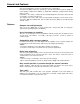
IMPORTANT “Unauthorized recording of copyrighted television programs, video tapes and other materials may infringe the right of copyright owners and be contrary to copyright laws.” WARNING: To reduce the risk of fire or shock hazard, do not expose this equipment to rain or moisture. I CAUTION: TO REDUCE THE RISK OF ELECTRIC SHOCK, DO NOT REMOVE COVER (OR BACK). NO USER-SERVICEABLE PARTS INSIDE. REFER SERVICING TO QUALIFIED SERVICE PERSONNEL.
Contents General and Features.....................................................4 Controls and their functions Controls and their functions...........................................6 • Front panel...................................................................7 • Connector area...........................................................11 • Tapes.........................................................................14 Time code Time code/user bit......................................................
General and Features This unit is a digital video cassette recorder which uses 1/4-inch tapes. It incorporates digital compression technology so that the deterioration in picture quality and sound quality resulting from dubbing is significantly minimized compared with existing analog systems. Furthermore, since it has a compact 4U size and light weight, the unit can be carried around or mounted in a 19-inch rack with ease.
Features (continued) Multi-function input/output interfaces • Analog input/output Component (Y, PB, PR) and composite and S-VIDEO signal input and output connectors are provided. • Digital audio input/output AES/EBU audio input/output is possible when the optional digital audio interface board (AJYA655P) is used. • Serial digital input/output Serial digital (SMPTE 259M-C, 272M) input/output is possible when the optional component serial interface board (AJ-YA750P) is used.
Controls and their functions Front panel Counter Display Section –6–
POWER switch When the ON side is pressed, the power is switched on, and the counter display lights up Cassette insertion slot The M cassette, L cassette and consumer cassette (S cassette) with adaptor are inserted into this slot. Consumer cassettes can be played back only. EJECT button When this is pressed, the tape is unloaded and several seconds later the cassette is automatically ejected. When the counter display indicates “CTL”, the display is reset.
Controls and their functions (continued) COUNTER/REMAIN button This switches between the tape counter tape time indicator and the remaining tape indicator. [r ***] is displayed in the case of the remaining tape indicator. After the cassette tape is inserted, [r ---] (--- flashes) is displayed until remaining tape is calculated, and [r EJ] (EJ flashes) when ejecting the tape. RESET button When this is pressed during CTL mode, the counter returns to the 00:00:00:00 display.
Headphones jack The sound being recorded, played back or edited can be monitored on stereo headphones when they are connected to this jack. Volume control This is used to adjust the headphones volume. Audio recording level controls These are used to adjust the recording levels of the analog audio signal CH1/CH2. CTL/TC/UB switch Use this switch when selecting the counter display. CTL: Tape timer (control signal) is displayed. TC: Time code is displayed. UB: User bit is displayed.
Controls and their functions (continued) SET button When this is pressed, the data which has been set on the setup menu is entered. After data entry, the setup mode is exited and the original operating mode is restored. DIAG button When this is pressed, VTR information is displayed. When it is pressed again, the original display is restored. There are two types of VTR information: “HOURS METER” information and “WARNING” information.
Connector area –11–
Controls and their functions (continued) AC IN connector This is for connecting the unit to the power outlet using the power cord provided. SIGNAL GND terminal This terminal is connected to the signa unit which is connected to the unit in order to reduce noise. It is not connected to ground for safety purposes. Fuse holder This contains a fuse. Fan motor This is for cooling the unit. The error code is displayed on the counter when trouble has caused the fan motor to stop.
S1/VIDE0 OUT connector This is the S-VIDEO output connector. ANALOG COMPONENT VIDEO OUT connector The analog component video signal is output from this connector. ANALOG COMPOSITE VIDEO OUT connectors The analog composite video signals are output from these connectors. The video signal with signals superimposed on it can be output from the VIDEO OUT3 connector. The superimpose function can be set ON or OFF on the setup menu No. 006 (SUPER).
Tapes Three types of tapes can be used with the unit. Type Description Consumer cassette (S cassette) Tape designed exclusively for the camcorders used by consumers in general. Only playback is possible using the optional cassette adaptor. Use of Panasonic consumer DV cassette tapes is recommended. Note that inserting a cassette tape without using the cassette adaptor can damage the unit. M cassette Recording/playback tape with a maximum capacity of 63 minutes.
When recording/playback using 1 unit Set the CONTROL switch on the front panel to LOCAL. • “DIGITAL” for serial component digital video signal input. • Set the VIDEO IN to ANALOG and select as following for the analog input: • “Y PB PR” for analog component video signal input. • “CMPST” for analog composite video signal input. • “S-VIDEO” for S-VIDEO signal input. –15– • “DIGITAL” for serial component digital audio signal input. • “AES/EBU” for digital audio signal input.
When recording, playback & editing with 2 units (deck to deck) The CONTROL switch on the recorder must be set to the LOCAL position, and the CONTROL switch on the player must be set to the REMOTE position. Set the VIDEO IN switch to the following position: • “SERIAL I/F” for serial component digital video signal input.* • “Y PB PR” for analog component video signal input. • “CMPST” for analog composite video signal input.
When using an editing controller For further details, refer to the Operating instructions of the AG-A850 editing controller (optional accessory).
Internal encoder adjustments In order to ensure error-free and accurate editing during AB roll editing (a method of editing using two source VTRs) using an editor, the ENCODER OUT controls must be adjusted after the system has been connected. (These controls must be re-adjusted each time the connecting cables are replaced or the connections are changed.) Connect the equipment as shown in the figure below.
Check the connections. (see previous page.) Select [OFF] on ENCODER SEL at the set up menu. (See page 27.) Select [ON] to operate the internal encoder externally. Adjust the SYSTEM PHASE. On the P1 VTR, play back a cassette tape on which standard color bar signals have been recorded. Adjust P1 VTR SYS PHASE. Adjust the controls to the following with the waveform monitor (WFM). 1) Expand WFM 0.1 µs on the INT mode. 2) Check the H SYNC position. 3) In this status, select EXT mode for the WFM.
Printed circuit board Printed circuit board Abbr. name F8 board SW1 ADDACUE SW61 F4 board SW400 Full name Function Factory setting Audio Input Impedance SW This sets the CH1 audio input impedance. HlGH/600Ω HIGH Audio Input Impedance SW This sets the CH2 audio input impedance. HlGH/600Ω HIGH Component PB/PR This sets the component PB/PR Output level output level when connecting with selector the editor.
Switching on the power/inserting the cassette Before starting to operate the unit, check whether the equipment has been connected properly. Turn on the power. Check that the error indicator is not displayed on the counter. Insert the cassette tape. Insert the tape at its proper position without force. (See page 14.) Check that the STOP lamp is on. When the tape is inserted, the drum rotates automatically, the tape is loaded and the unit goes into the stop mode.
STOP mode When the STOP button is pressed, the unit goes into the stop mode. The STOP lamp lights and the tape stops traveling. • In order to protect the tape, the unit goes into the standby OFF mode after the time set by setting menu No.400 (STILL TIMER) has elapsed. When the STOP, REW, FF or PLAY button is pressed, the unit will go into the appropriate mode.
Recording Set the accidental erasure prevention tab on the cassette tape to the “recording” position and insert the tape. Press the STOP button to place the unit in the stop mode. Check that the REC INHIBIT lamp is off. Select the video and audio input signals and adjust their levels. 4-1 Selecting video/audio input signals 1 Connect the signals to be recorded. 2 Select the input signals using the INPUT SELECT switches on the front panel.
Playback Insert the cassette tape, and place the unit in the stop mode. Press the PLAY button. Regular playback is now commenced. To end playback, press the STOP button. The VTR now goes into the stop mode. • Check that the SERVO lamp is lighted during playback. If it flashes or if it is off, the images played back will be disturbed.
Setup (default settings) The unit’s major settings are performed. by making selections on menus. The setting menus appear on the TV monitor when the TV monitor and VIDEO OUT 3 connector in the unit’s connector area are hooked up. Changing the settings Press the MENU button. The setup menu appears on the TV monitor and setup menu No. appears on the counter display. (If the setup has already been performed, the screen showing the changes made last will appear.) , and select the item to be set.
Setup (setting) menus This unit can store up to 5 user files (user 1 to user 5) containing different menu settings, and these files can be selected and used. Changing the file Press the MENU button. Hold down the FILE button and press the cursor button file. Hold down the FILE button and press the cursor button user file. to switch to the next user to switch to the previous USER FILE Each user file contains the following items.
SYSTEM menu Item No. 00 01 Superimposed display Setting No. SYS SC COAR. 0000 0001 0002 0003 0 90 180 270 SYS SC FINE 0000 -127 0127 02 SYS H Description Superimposed display 0 0255 0000 127 -112 0112 0 0224 112 00 ENCODER SEL 0000 0001 OFF ON 10 AV PHASE 0000 -128 0128 0 0255 127 System phase rough adjustment: 90° units When shipped from the factory, the setting values do not change even if setting operations are performed.
Setup (setting) menus USER menu (continued) Item No. Superimposed display Setting No. Description Superimposed display 0000 0 0018 18 0022 22 003 DISPLAY SEL 0000 0001 0002 TIME T&STA T&S&M This selects what information is to be provided by the time code and other super displays output to the VIDEO 3 connector. 0: Time only. 1: Time and status. 2: Time, status and mode. The mode display is DVCPRO mode display during DVCPRO format and DV mode display during DV format.
USER menu (continued) Setting Item No. Superimposed display No. Description Superimposed display 0000 0001 0002 X 32 X 60 X 100 This sets the maximum speed for FF and REW operations. 0: 32× normal speed 1: 60× normal speed 2: 100× normal speed During DV format, the maximum speed is 32× normal speed regardless of this setting.
Setup (setting) menus USER menu (continued) Item Setting No. Description No. Superimposed display Superimposed display 112 AUTO REW 0000 0001 OFF ON This selects whether to rewind the tape automatically to the tape start when the tape end is detected. 0: The tape stops at the tape end. 1: The tape is rewound to the tape start.
USER menu < E D I T > Setting Item Description No. Superimposed display No. 300 VAR RANGE 0000 0001 – 0.43 – 1 – 4 – +4 This sets the VAR speed range. 0: The tape is played in slow motion at a speed ranging from – 0.43× to +1× normal speed. 1: The tape is played in the ±4.1× normal speed range. Phase synchronization from the editing controller is no longer possible once this item has been set to “0”. For DV format: When using the dial on the front panel, playback is always performed at – 0.
USER menu (continued) Item Setting Description No. Superimposed display No. Superimposed display 307* EDIT RPLCEC 0000 0001 0002 0003 N-DEF CH1 CH2 CH1+2 This sets the channel assignments for the controller’s analog audio preset when editing the digital audio of the VTR using a controller which does not have a digital audio edit preset control function.
Setup (setting) menus USER menu
USER menu
Setup (setting) menus USER menu
USER menu
USER menu
Time code/user bit Time code The time code is used when the time code signal generated by the time code generator (time code signal generator) is to be recorded on the tape, its values are to be read by the time code reader (time code signal reader), and the absolute position of the tape is to be displayed in increments of hours, minutes, seconds and frames. The time code is written in the sub-code area (data area) of the helical track.
Recording internal/external time codes Setting the internal time code Place the VTR in the stop mode. Set the CTL/TC/UB switch to TC. Set the TC lNT/EXT switch to INT. (Internal time code selected) Set the RUN MODE. (setup menu No. 510) The time code runs at the same time as the recording proceeds. REC (RUN): FREE (RUN): The time code runs in the same way as the time regardless of the VTR’s operation. Set the REGEN MODE. (setup menu No.
Reproducing the time code/user bit Place the unit in the stop mode. Set the CTL/TC/UB switch to TC or UB. TC: The time code is displayed. UB: The user bit is displayed. • When it is no longer possible to read the time code, it is interpolated using the CTL signal. Press the PLAY button. Playback now commences, and the time code appears on the display. When setting menu No.006 (SUPER) is ON, the time code value is superimposed onto the video signal from the VIDEO OUT 3 connector.
Superimpose screen The control signals, time code, etc. are displayed using abbreviations. CTL = control signal TCR = TC time code reading UBR = TC user bit reading TV monitor Characters displayed The background of characters superimposed on the display can be changed using menu No.007 (CHARA TYPE). TV monitor Display position The position of the characters superimposed on the display can be changed using setting menus No.001 (CHARA H-POS) and No.002 (CHARA V-POS).
Servo reference This unit automatically selects the input video signal selected by the INPUT switch, the reference video signal supplied from the REF VIDEO input connector or the internal sync signal as the servo reference signal. When the signal is selected, the unit’s mode and servo reference stand in the relationship shown in the flowchart presented below.
Servo reference setting tables The servo reference signal is switched as shown in the tables below depending on the servo reference setting, deck mode and what input signal is available. When the mode is transferred to editing or recording/playback, the image may be disturbed and the transfer may be delayed if the references during playback and recording do not match. During playback or special playback SERVO REF on the setup menu No.
Audio V Fade Function (AJ-D650 only) When editing tapes, the edit point splicing selection (setting menu No. 309 and 310) information is recorded on the tape. This information is then sensed during playback, and V fade or cut processing is automatically performed for these sections. [However, only when the playback fade selection (No. 719) is AUTO.] When the edit point splicing selection (setting menu No. 309 and 310) is CUT Audio signal A Audio signal B Noise may appear at the edit splice.
Rack mounting The unit can be mounted into a 19-inch standard rack if the optional rack-mounting adaptors (AJ-MA75P) are used. For the installation rails, it is recommended that the rail and bracket for 18" length (model number CC3001-99-0400) of SHASSIS TRAK be used. (The complete slide rail and bracket unit is not available from Panasonic) For further details, consult with your dealer. Remove the screws on the left and right sides of the unit.
Video head cleaning This unit has an auto head cleaning function which automatically reduces the dirt on the heads. However, to further increase the unit’s reliability, it is recommended that its video heads be cleaned every day. Use the cleaning fluid designated by Panasonic. Condensation Condensation occurs due to the same principle involved when droplets of water form on a window pane of a heated room.
Error messages Warning Error No. TV monitor display* Descriptions VTR operation E-00* (Err-00) SERVO NOT LOCKED Error No. lights when servo disturbances continue for 3 or more seconds during playback, recording or editing. Continued E-01* (Err-01) LOW RF Error No. lights when envelope levels approx. 1/3 that of normal levels are detected for more than 1 sec. during playback, recording or editing. Stop E-10* (Err-10) FAN STOP Error No. lights when a fan motor stops operating.
Error messages Error No. Descriptions VTR operation E-57 The start/end processing operation is not completed even after 10 or more seconds have elapsed. Stop The cylinder motor speed is abnormally low. E-59 Stop The cylinder motor speed is abnormally high. E-60 Stop The capstan motor speed is abnormally low. E-61 Stop The tape-up reel motor speed is abnormally high. E-67 Stop An abnormal torque applied to the take-up reel motor is detected.
Connector signals VIDEO IN Active through (Option) SERIAL IN (DIGITAL) Y, PB, PR (ANALOG) BNC×2 BNC×3 VIDEO IN BNC×2 Loop-through, 75 Ω termination switch provided REF VIDEO IN BNC×2 Loop-through, 75Ω termination switch provided S1-VIDEO IN 4-pin × 1 SERIAL OUT (DIGITAL) Y, PB, PR (ANALOG) VIDEO OUT S1-VIDEO IN BNC × 3 BNC × 3 BNC × 3 4-pin × 1 (Option) SERIAL IN (DIGITAL) AUDIO IN (DIGITAL) BNC × 2 BNC × 1 (Option) CH1/CH2 AES/EBU format (Option) AUDIO IN (ANALOG) TIME CODE IN XLR × 2 BNC
Connector signals RS-232C REMOTE (25-pin D-SUB straight cable supported) Description Circuit Pin No. Abbreviation 1 FRAME GROUND Protective ground Frame ground 2 T×D Transmitted data Receives data from the PC. 3 R×D Received data Sends data to the PC. 4 RTS Request to send Shorted with pin 4. 5 CTS Clear to send Shorted with pin 5.
Specifications (Video output connector) GENERAL Analog component output: Power supply: Power consumption: AC 120 V, 50–60 Hz 150 W Analog composite output: Operating ambient temperature: Operating ambient humidity: Weight: Dimensions (W×H×D): Recording format: Recording tracks: Tape speed: Recording time: Tape: FF/REW time: Search speed: Digital slow motion: Editing accuracy: Tape timer accuracy: Servo lock time: 41°F to 104°F (5°C to 40°C) 10% to 90% (no condensation) 35.
Panasonic Broadcast & Television Systems Company Division of Matsushita Electric Corporation of America Executive Office: One Panasonic Way (4B-7), Secaucus, NJ 07094 REGIONAL OFFICES: New Jersey: One Panasonic Way, Secaucus, NJ 07094 EASTERN: Sales: Panazip 4B-7 (201) 348-7671 Washington, D.C. (703) 759-6900 SOUTHERN: 1225 Northbrook Parkway, Suite 107A, Suwanee, GA 30174 Sales: (404) 717-6772 CENTRAL: 1707 North Randall Road, Elgin, IL 60123 Panazip EIC-3 Sales: (708) 468-5160 WESTERN: 4001 W.
Reference Guide • Items supporting DVCPRO/DV/DVCAM tape playback • Items supporting RS-232C Applicable models
Thank you for purchasing this product. This booklet describes the items which support both DVCPRO/DV/DVCAM tape playback and RS-232C. Read it together with the Operating Instructions. Contents Items supporting DVCPRO/DV/DVCAM tape playback . . . . . . . . . . E-2 Cautions when playing back consumer DV tapes and DVCAM tapes . . . . . E-2 DVCPRO/DV/DVCAM displays . . . . . . . . . . . . . . . . . . . . . . . . . . . . . . . . . . . . . E-2 Additional set-up menu items . . . . . . . . . . . . . . . . . . . .
Additional set-up menu items USER menu DVCPRO/DV/DVCAM tapes can be played back by selecting the item No.108 “FORMAT SEL” setting. Setting Item No. 108 Superimposed display No. FORMAT SEL 0000 0001 0002 Description of setting Superimposed display DVCPRO These settings are for selecting the format when an L DV cassette or S cassette is used. DVCAM The selected setting only becomes valid immediately after the cassette has been inserted.
Items supporting RS-232C Additional set-up menu items Setting Item No. Superimposed display No. 204 RS232C SEL 0000 0001 Description of setting Superimposed display OFF These settings are for selecting whether the RS-232C ON connector is to function when the REMOTE/LOCAL switch is set to REMOTE. 0: Connector does not function. 1: Connector functions. 205 BAUD RATE 0000 0001 0002 0003 0004 0005 300 These settings are for selecting the RS232C 600 communication speed (baud rate).
2. Hardware specifications 1) External interface specifications For the model AJ-D750 (1) Connector specifications Connector: D-SUB 25-pin (crossover cable supported) Pin No. Signal 1 FG 2 Circuit name Description Protective ground Frame ground RXD Received data Data is sent to PC. 3 TXD Transmitted data Data is received from PC. 4 CTS Clear to send Shorted with pin 5. 5 RTS Request to send Shorted with pin 4.
For the models AJ-D650 and AJ-D640 (1) Connector specifications Connector: D-SUB 25-pin (straight cable supported) Description Circuit name Pin No. Signal 1 FG Protective ground Frame ground 2 TXD Transmitted data Data is received from PC. 3 RXD Received data Data is sent to PC. 4 RTS Request to send Shorted with pin 5. 5 CTS Clear to send Shorted with pin 4.
3. Software specifications 1) Protocol (1) Communication parameters Communication system Asynchronous, full duplex Communication speed 300/600/1200/2400/4800/9600 Bit length 7 bit/8 bit Stop bit 1 bit/2 bit Parity bit NONE/ODD/EVEN ACK code ACK code returned/ACK code not returned The ACK code is what is returned from the VTR to the controller when data has been successfully sent from the controller. The underlining indicates the factory settings.
(2) Send format [controller (PC) VTR] Data format [STX] [command] [:] [data] [ETX] 02h XX XX XX 3Ah XX-XX 03h (ASCII code: symbols, numbers, upper-case letters) 20h
(3) Return format [VTR controller (PC)] The following responses are made to the command. If necessary, more than one response is made. When the communication has terminated normally 1. The receive completion message is returned. [ACK] 06h 2. The execution completion message is returned. [STX] [command] [data] [ETX] 02h XX XX XX XX-XX 03h • [command] • [data] Example: :This is the message (data) which is returned or the execution completion message identifier. :This is the data to be returned.
5. Command table 1) Commands relating to operation control • As for the return (completion) message, [ACK] is first returned when data is received, and the execution message is subsequently returned. It is only the execution message which is listed in this table. • In the case of commands not listed in the table, ER001 (invalid command) is returned after [ACK] has been returned.
VTR operation SHTL FORWARD Send command Return (completion) message [STX] OSF:data [ETX] [STX] OSF [ETX] data = n: speed data 0: STILL 1: ×0.03 (DVCPRO), ×0.03 2 : ×0.1 (DVCPRO), ×0.1 3 : ×0.2 (DVCPRO), ×0.3 4 : ×0.5 (DVCPRO), ×0.5 5 : × 1 (DVCPRO), ×1 6: ×1.85 (DVCPRO), ×1.85 7 : ×4.1 (DVCPRO), ×3.1 8 : ×9.5 (DVCPRO), ×9.5 9 : ×16 (DVCPRO), ×16 A : ×32 SHTL REVERSE (DVCPRO), ×32 [STX] OSR:data [ETX] data = n: 0: 1: 2: 3: 4: 5: 6: 7: 8: 9: A: ×32 ×0.03 ×0.1 ×0.3 ×0.5 ×1 ×1.85 ×3.1 ×9.
2) Commands relating to inquiries • As for the return (completion) message, [ACK] is first returned when data is received, and the execution message is subsequently returned. It is only the execution message which is listed in this table. • In the case of commands not listed in the table, ER001 (invalid command) is returned after [ACK] has been returned.
3) Microsoft QuickBASIC sample program CLS STX$ = CHR$(&H2): ETX$ = CHR$(&H3): NAK$ = CHR$(15): ACK$ = CHR$(&HG) PRINT "*** RS-232C COMMUNICATION SAMPLE PROGRAM ***" PRINT "Type Command ’QUIT’ to quit.