
Operating Instruction Digital Video Cassette Recorder AJ-D650


For the models AJ-D650 and AJ-D640
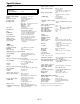
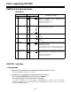
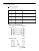
(1) Connector specifications
Connector: D-SUB 25-pin (straight cable supported)
Pin No. Signal
Circuit name
Description
1
FG
Protective ground
Frame ground
2
TXD
Transmitted data
Data is received from PC.
3 RXD
Received data
Data is sent to PC.
4
RTS
Request to send
Shorted with pin 5.
5
CTS
Clear to send
Shorted with pin 4.
6
DSR
Data set ready
+ voltage output after communication enable status
7
SG
Signal ground
Signal ground
20
DTR
Data terminal ready
No processing
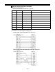
(2) Example of connection with controller (PC)
(Using straight cable with D-SUB 25-pin connectors)
PC side
(D-SUB 25-pin connector)
VTR side
(Using straight cable with D-SUB 9-pin and 25-pin connectors)
PC side
(D-SUB 9-pin connector)
VTR side
–E-6–