For your safety IMPORTANT Operating precaution “Unauthorized recording of copyrighted television programmes, video tapes and other materials may infringe the right of copyright owners and be contrary to copyright laws.” Operation near any appliance which generates strong magnetic fields may give rise to noise in the video and audio signals. If this should be the case, deal with the situation by, for instance, moving the source of the magnetic fields away from the unit before operation.
For your safety CAUTION RISK OF ELECTRIC SHOCK DO NOT OPEN CAUTION: TO REDUCE THE RISK OF ELECTRIC SHOCK, DO NOT REMOVE COVER (OR BACK). NO USER SERVICEABLE PARTS INSIDE. REFER TO SERVICING TO QUALIFIED SERVICE PERSONNEL. The lightning flash with arrowhead symbol, within an equilateral triangle, is intended to alert the user to the presence of uninsulated “dangerous voltage” within the product’s enclosure that may be of sufficient magnitude to constitute a risk of electric shock to persons.
Contents Introduction . . . . . . . . . . . . . . . . . . . . . . . 5 Setup (initial settings) . . . . . . . . . . . . . . .24 Features . . . . . . . . . . . . . . . . . . . . . . . . . . .5 Setting method using the on-screen menus . . . . 24 Returning to the factory settings . . . . . . . . . . . . . 24 Setting the user defaults . . . . . . . . . . . . . . . . . . . 25 Loading the user defaults . . . . . . . . . . . . . . . . . . 26 Menu protection . . . . . . . . . . . . . . . . . . . . . . . . .
Introduction The AJ-HD1200A multi-format digital video cassette player is capable of playing not only all types of materials ranging from HD (DVCPRO HD and DVCPRO HD-LP) to SD (DVCPRO50, DVCPRO50P and DVCPRO) recorded in the DVCPRO formats on 1/4-inch wide compact cassette tapes but also consumer DV and DVCAM tapes. A down-converter provided as a standard feature verifies all tapes, whatever their format, using analog composite output signals.
Features SD down-converter The unit comes with a built-in SD down-converter as a standard feature to enable the output of SD SDI signals2 and analog composite signals at the same time as HD SDI output signals2 and for monitoring the signals on an SD monitor. Up-converter function2 When an SD format tape is played back, it is possible to up-convert the signals to the HD format while at the same time outputting the signals in the SD format.
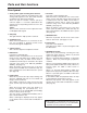
Parts and their functions Front panel Counter display 67 8 5 REC INH REMOTE dB -30 -25 -20 -16 -12 -8 -4 - DV < 4 : SCH SERVO CTL TC UB 0 CH 1 CH 2 HOURS ; 9 MINUTES < SECONDS FRAMES = 1 2 3 EJECT POWER ON OFF @ LOCAL REMOTE AUDIO SELECT INPUT ? ANALOG CH 1 C CH 3-4 PULL FOR VAR 720 P OFF ON REC INH (OPTION) CH 2 REC CH 3 MENU METER CH1·2 CH3·4 REW STOP FF SEARCH PLAY PAUSE/STILL REC(OPTION) TAPE CH1 ST CH2 AUDIO MON SELECT E F Q CH 4 RESET P AUDIO OU
Parts and their functions Front panel 6 REPEAT lamp This lights during repeat playback. The lamp flashes and repeat playback is not performed if the counter display mode which has been set using menu items No.161 [CTL (TC) BGN] and No.162 [END] is at variance from the counter display mode used for repeat playback. 7 SYSTEM format lamp This indicates the status of the mode which has been selected by menu item No.15 [SYSTEM FREQ].
Parts and their functions Front panel ? ANALOG lamp2 This lights when ANALOG is selected for the audio input signals as the menu item No.700 [AUDIO IN SEL] setting. When it is off, the HD SDI signal input or INT SG status is established. The signals which are input for each of the channels when analog signals are supplied are recorded on the following audio tracks of the tape.
Parts and their functions Front panel C Analog audio signal recording level controls2 These are used to adjust the recording levels of the analog audio signals for CH1, CH2, CH3 and CH4 (coupled to CH5, CH6, CH7 and CH8). These are “pull for variable” controls: pull up a control to adjust it. If a control is pulled down, the signals of the corresponding channel are set to the default level. These controls cannot be used to adjust the levels of HD digital audio signals.
Parts and their functions Front panel M REC button2 No optional board installed This unit is a video cassette player so it cannot record by pressing the REC button. When the REC button is pressed, the REC INH lamp on the counter display lights for several seconds. When T&S&M has been selected as the menu item No.006 [DISPLAY SEL] setting, “NO OPTION FOR REC” appears in the superimposed mode display area.
Parts and their functions Rear panel ? = 5 8 7 6 TC HD/SD REF VIDEO IN IN (OPTION) = VIDEO OUT 1 Y/G PB/B 75Ω ON (OPTION) PR/R OFF OUT AUDIO OUT CH 1 CH 2 3 2(SUPER) AUDIO IN (OPTION) PUSH PUSH CH 1 CH 2 AUDIO MON OUT L DC OUT 12V 250mA AC IN > FUSE 250V T2.5AH F1 R CH 3 CH 4 PUSH CH 3 PUSH CH 4 R E M O T E DC IN L MONITOR R 9 : 1 AC IN inlet This is the AC power inlet. Connect the accessory power cable here.
Parts and their functions Rear panel 5 VIDEO OUT (1, 2, Y/G, PB/B, PR/R) connectors By changing the menu item No.615 [V OUT SEL] setting, either analog composite video signals or HD analog component Y (or G) signals are output from the VIDEO OUT1 connector. By selecting the menu item No.616 [OUT MATRIX] setting, Y/PB/PR or R/G/B signals can be selected as the HD analog component signals. Video signals with superimposed information embedded can be output from the VIDEO OUT2 connector.
Tapes Inserting the tape Align the cassette with the center of the slot and push it gently inside. The cassette tape is loaded automatically.
Operation Turning on the unit’s power STOP mode O If the same locations on the same tape are repeatedly used, the cumulative standby time at these same locations will continue to mount up. To protect your tapes, minimize the amount of standby time at the same locations on the tapes.
Operation Recording 6 This function can be used only when the AJ-YA120AG (optional accessory) has been installed. 1 2 3 4 5 16 Set the cassette tape’s erasure prevention tab to recording enable, and insert the tape. Press the STOP button to set the unit to the STOP mode. Selecting the input video signals Use menu item No.600 [VIDEO IN SEL] to select the video input signals. 1. Selecting the input audio signals 1) Connect the signals to be recorded. 2) Use menu item No.
Operation Playback 1 2 3 Insert a cassette tape into the unit. Press the PLAY button. Normal playback now commences. To end playback, press the STOP button. The VTR is set to the stop mode. O Check that the SERVO lamp remains lighted during recording. When it flashes or it is off, the playback images will be disrupted. O When playback starts up, the images will be disrupted for a moment.
Operation Variable speed playback Linear 0.3k playback (when AJ-A95 is connected) The unit is set to the slow still mode when the SEARCH button is pressed during still image playback (PLAY PAUSE). When the FF or REW button is now pressed, the tape is played back at the linear 0.3k speed. Pressing the PAUSE/STILL button during linear 0.3k playback will pause the tape. When the PAUSE/STILL button is pressed again, linear 0.3k playback resumes.
Operation Repeat playback Setting the BEGIN and END points Setting the repeat playback mode 1 1 2 3 4 5 6 7 Set the VTR to the menu mode. (This is done by setting the LOCAL/MENU/ REMOTE switch to the MENU position). Select menu item No.161 [CTL (TC) BGN] or No.162 [END], and press the DATA+ button (PAUSE/STILL button) or DATA- button (PLAY button). Whether a setting is to be entered can be selected by operating the DATA+ button and DATA– button.
Time code & user’s bit Time code 4 The time code signals generated by the time code generator (time code signal generator) are recorded on the tape, and their values are read by the time code reader (time code signal reader) to indicate absolute positions on the tape in increments of hours, minutes, seconds and frames. The time code itself is written in the sub code area (data area) of the helical track.
Time code & user’s bit Setting the user’s bit This function can be used only when the AJ-YA120AG (optional accessory) or AJ-YAD120AG (optional accessory) is installed. 1 2 Set the VTR to the menu mode. (This is done by setting the LOCAL/MENU/ REMOTE switch to the MENU position). Select menu item No.531 [UB PRESET]. Playing back the time code and user’s bit 1 2 3 The following steps are the same as for setting the time code. Set the unit to the STOP mode. Set the COUNTER button to TC or UB.
Superimposed screen displays The control signal, time code, etc. are displayed on the TV monitor in the form of abbreviations when the unit’s VIDEO OUT2 connector is connected to a TV monitor. In addition, when the optional AJ-YA120AG is installed, the connector from which the superimposing is output can be changed using the menu item No.005 [SUPER] setting.
Superimposed screen displays Operation mode TIME mode What data is to be displayed can be selected using menu item No.006 [DISPLAY SEL].
Setup (initial settings) This unit’s main settings can be performed and checked using the on-screen menus which are displayed on the video monitor connected to the unit. It is also possible to perform and check the settings using the item numbers and setting numbers which are indicated on the front panel display. Furthermore, a user setting memory in which to store one set of settings is provided, enabling the desired settings to be stored for future use.
Setup (initial settings) 3 Press the MENU-UP button or MENU-DOWN button to move the cursor to the LOAD position, and press the SET button. The unit is set to the LOAD mode, and the LOAD screen appears on the video monitor. 4 SET–UP MENU 2 NO FACTORY USER (ALL) USER (NOT SYSTEM) 4 5 Press the MENU-UP button or MENU-DOWN button to move the cursor to the FACTORY position, and press the SET button.
Setup (initial settings) Loading the user defaults Menu protection 1 By setting the unit to the menu protection mode, the setup menu can no longer be opened even when the LOCAL/MENU/REMOTE switch is set to the MENU position. 2 Set the LOCAL/MENU/REMOTE switch to the MENU position. The unit is set to the menu setting mode, and the menu screen appears on the video monitor. Press the RESET button.
Setup (initial settings) 5 Set the LOCAL/MENU/REMOTE switch to the LOCAL or REMOTE position. The unit is now set to the menu protection mode. When the LOCAL/MENU/REMOTE switch is set to the MENU position, the unit is not set to the menu setting mode, and “MENU PROTECTED” appears on the video monitor screen. Displaying the DIAG menu The unit comes with a function for displaying the “hour meter,” “software version” and “deck serial No.” on the video monitor.
Setup menus Menus which are displayed The menus displayed differ depending on the setting selected for menu item No.25 [SYSTEM FREQ] and on the optional boards (AJ-YA120AG, AJ-YAD120AG) which have been installed. No.
Setup menus No.
Setup menus No.
Setup menus SYSTEM Item No. “ Superimposed display Setting No. Superimposed display Description of settings 12 SYS H (HD) 0000 : 1100 : 2200 –1100 : 0 : 1100 For adjusting the system phase of the HD SDI output signals (in 13.5 ns increments). –: The phase is advanced. +: The phase is delayed.
Setup menus SYSTEM Item No. 25 Superimposed display Setting No. SYSTEM FREQ 0000 0001 20002 20003 20004 26 Superimposed display Description of settings For selecting the system frequency 59/60 0: The 59.94 Hz or 60 Hz system frequency is selected. 50i/25P 1: The 50 Hz or 25 PsF system frequency is selected. At this setting, the 1080/25 PsF format signals can be recorded and played back in the same way as with the 1080/50i format. 223/24 2: The 23.98 Hz or 24 Hz system frequency is selected.
Setup menus BASIC Item No. 001 Superimposed display Setting No. Superimposed display LOCAL ENA For setting the buttons on the front panel which can be operated when the LOCAL/MENU/REMOTE switch is at the REMOTE position. DIS 0: None of the buttons can be operated. ST&EJ 1: Only the STOP and EJECT buttons can be operated. ENA 2: All of the buttons with the exception of COUNTER and RESET can be operated.
Setup menus BASIC Item No. 006 Superimposed display Setting No. Superimposed display DISPLAY SEL 0000 0001 0002 0003 0004 0005 0006 0007 0008 0009 Description of settings For setting what the information to be superimposed. TIME 0: Only the data is displayed. (“Data” refers to the CTL, TC or UB value selected by the COUNTER button.) T&STA 1: The data and operation status are displayed. T&S&M 2: The data, operation status and mode are displayed. T&RT 3: The data and REC TIME are displayed.
Setup menus BASIC Item No. 020 Superimposed display Setting No. Superimposed display SYS FORMAT For setting the format in which to record or play back the signals including the HD REF signals. 1080i 0: 1080i mode 720p 1: 720p mode 0000 0001 022 PB FORMAT 0000 0001 023 030 For setting the format in which to play back the tape. MANUAL 0: The tape is played back in the format selected by the menu item No.020 [SYS FORMAT] setting.
Setup menus Formats for playback Depending on how the menu item No.020 [SYS FORMAT], No.022 [PB FORMAT] and No.023 [FORMAL SEL] settings are combined, the formats of the tapes played back by the unit differ as shown in the table below. 022. PB FORMAT 020. SYS FORMAT 1080i 023.
Setup menus OPERATION Item No. 101 Superimposed display Setting No. Superimposed display SHTL MAX For setting the maximum speed in the shuttle mode when using the external controller connected to the 9-pin remote connector. X8.4 0: 8.4k normal speed X16 1: 16k normal speed X32 2: 32k normal speed The maximum speed for the HD SP mode is automatically limited to 25k normal speed. 0000 0001 0002 102 For setting the maximum speed of fast forward or rewind operations.
Setup menus OPERATION Item No. 110 Superimposed display Setting No. Superimposed display AUTO REW 0000 0001 112 FRZ MODE SEL 0000 0001 114 REC INH LAMP 0000 0001 115 118 150 152 EJECT SW INH 0000 0001 0000 0001 For setting the search still, cue and review speed. X4.1 0: 4.1k normal tape speed X8.4 1: 8.
Setup menus OPERATION Item No. Superimposed display Setting No. Superimposed display 161 CTL BGN or TC BGN For setting the BEGIN point in the repeat playback mode. Either TC or CTL is set as the counter display mode using the COUNTER button. If no mode is set, – – : – – : – – : – – appears, and the tape start serves as the BEGIN point. 162 END For setting the END point in the repeat playback mode. Either TC or CTL is set as the counter display mode using the COUNTER button.
Setup menus INTERFACE Item No. 202 Superimposed display Setting No. Superimposed display ID SEL Description of settings For setting the ID information to be returned to the controller. OTHER 0: The ID information of the VTR other than DVCPRO is set. DVCPRO 1: The DVCPRO ID information is set. ORIG 2: Set this only when the unit is connected to a Panasonic controller (such as the AJ-A900, optional accessory).
Setup menus TIME CODE Item No. 500 Superimposed display Setting No. Superimposed display VITC BLANK 0000 0001 For setting whether to output the VITC signal at the position which is set using menu items No.501 [VITC POS-1] and No.502 [VITC POS-2]. BLANK 0: The VITC signal is not output. THRU 1: The VITC signal is output. This setting takes effect only with the SD output (VIDEO output and SD SDI output).
Setup menus TIME CODE Item No. 508 Superimposed display Setting No. Superimposed display BINARY GP 0000 0001 0002 0003 0004 0005 0006 0007 509 510 511 512 PHASE CORR 0000 0001 0000 0001 For selecting whether to set the CF flag of the TCG to ON. OFF 0: The CF flag is set to OFF. ON 1: The CF flag is set to ON. 0000 0001 For selecting whether to use the DF or NDF mode for CTL and TCG. DF 0: The drop frame (DF) mode is used. NDF 1: The non-drop frame (NDF) mode is used.
Setup menus VIDEO Item No. 600 Superimposed display Setting No. Superimposed display VIDEO IN SEL 0000 0001 0002 601 VIDEO INT SG 0000 0001 0002 0003 0004 0005 602 SDI IN MODE 0000 0001 603 604 615 616 620 621 626 627 “ For selecting the video signals to be input. INTSG 0: The internal signal selected by VIDEO INT SG is generated. HDSDI 1: The serial video signal supplied to the HD SDI IN connector is selected.
Setup menus VIDEO Item No. 628 629 630 Superimposed display Setting No. U/C ENH H 0000 0001 For enhancing the horizontal outlines during up-conversion. 0dB 0: 0dB +1dB 1: +1dB 0000 0001 For enhancing the vertical outlines during up-conversion. 0dB 0: 0dB +1dB 1: +1dB U/C ENH V 1080i>HD_OUT 0000 0001 632 720p>HD_OUT 0000 0001 634 636 676 680 681 682 0000 0001 For selecting the HD output signal format during 480i tape (DVCPRO50, DVCPRO, DV or DVCAM) playback.
Setup menus VIDEO Item No. 684 Superimposed display No. Superimposed display EDH (SD) 2DW 685 Setting 0000 0001 ESR MODE (SD) 0000 0001 0000 0001 For selecting the cross color processing during playback. OFF 0: The cross color is output as is. AUTO 1: The cross color can be reduced. CCR MODE (SD) 2DW 687 For setting whether to superimpose EDH onto the SD SDI output. OFF 0: EDH is not superimposed. ON 1: EDH is superimposed.
Setup menus AUDIO Item No. 700 Superimposed display Setting No. Superimposed display AUDIO IN SEL 0000 0001 0002 Description of settings For setting the audio signal input (in all the channels simultaneously). INTSG 0: The internal signal is generated. ANA 1: The input is fixed to analog signals. SDI 2: The input is fixed to SDI signals. O The input signals of the channels when analog signals are supplied are recorded onto the audio tracks below on the tape.
Setup menus AUDIO Item No. 730 Superimposed display Setting No. Superimposed display REC CUE 0001 0002 0003 0004 0005 0006 0007 0008 0009 0010 0011 0012 0013 731 732 759 760 762 CH1 CH2 CH3 CH4 CH5 CH6 CH7 CH8 CH1+2 CH3+4 CH5+6 CH7+8 CH1~8 PB FADE 0000 0001 0002 0000 0001 For setting whether to superimpose audio data onto the HD SDI output and SD SDI output. OFF 0: The audio data is not superimposed. ON 1: The audio data is superimposed.
Setup menus AUDIO Item No. 770 771 780 Superimposed display Setting No. Superimposed display MONITOR MIX 0000 0001 For setting the audio monitor output sound. (This functions when the audio monitor selector switch on the front panel is at the ST position.) STEREO 0: The sound is output in stereo. CH1+2 1: Mixed sound is output (to both the left and right connectors). 0000 0001 For setting the headphone output sound.
Setup menus DIF (This menu appears only when the AJ-YAD120AG board is installed.) Item No. 880 Superimposed display Setting No. DIF SPEED 0000 0001 0002 Superimposed display Description of settings For setting the transfer speed of the digital video interface output. S100 0: 100 Mbps When S100 has been selected as this item’s setting, DVCPRO S200 1: 200 Mbps HD format signals cannot be input or output. S400 2: 400 Mbps 882 DIF IN CH 0000 : 0063 0064 0 For setting the input channel.
Error messages When something goes wrong with the unit, one of the following error messages will appear on the front panel’s counter display and on the monitor’s superimposed display. With a superimposed display, the error number will appear in the counter value display area. Error No. Error message and description –d– DEW When dew (condensation) has been detected, the error number flashes, and the unit is transferred to the EJECT mode.
Error messages Error No. Error message and description E – 51 FRONT LOAD ERROR This appears when the take-up reel turns without engaging the tape for the prescribed period of time in the start end processing operation while the tape is loading (at the half-loading position). E – 52 W-UP REEL NOT ROTA This appears when the take-up reel has failed to take up the tape while the tape is running in the status where the total tape duration is undetected after the cassette was inserted.
Error messages Error messages which may appear when the AJ-YAD120AG board is installed Error No. Error message and description E – 04 UNKNOWN SIG This appears when the format of the signals supplied to the digital video interface is neither DVCPRO nor DV. It also appears when two AJ-HD1200A units are used as the input and output units and different settings are selected for the menu item No.25 [SYSTEM FREQ] of the two units. Operation performed by AJ-HD1200A Operation is continued (21).
Video head cleaning This unit comes with an auto head cleaning function which reduces the amount of dirt on the heads automatically. However, in order to improve the unit’s reliability, it is recommended that the video heads be cleaned on a daily basis. Use the cleaning fluid specified by Panasonic. Maintenance Before proceeding with maintenance, set the power switch to OFF, and be absolutely sure to hold the molded part of the power plug to disconnect it from the power outlet.
Specifications [GENERAL] Power supply: AC (100-240) V, 50/60 Hz DC 12V, 6.6 A Power consumption: 69 W (main unit only) 97 W (when AJ-YA120AG, AJ-YAD120AG are installed) indicates safety information. Ambient operating temperature: 41°F to 104°F (5°C to 40°C) Ambient operating humidity: 10% to 80% (no condensation) Weight: 17.38 lb (7.9 kg) Dimensions (WkHkD): 8 7/16k5 1/4k16 7/8 inches (214k132k428 mm) Recording format21, 22: DVCPRO HD-LP Recording video signals21, 22: 1080i/59.94 Hz, 720p/59.
Specifications $ Video output adjustment ranges HD serial digital output system phase21: 1080i: ±0.5H (in 13.5ns increments) 59/60 Hz: ±1100 samples 50 Hz: ±1320 samples 23/24 Hz: ±1375 samples 720p: ±0.5H (in 13.5ns increments) 59/60 Hz: ±825 samples SD serial digital/composite video output system phase21: ±0.5H (in 37ns increments) 59 Hz: ±858 samples 50 Hz: ±864 samples Composite video output SC phase; ±180 deg.
PANASONIC BROADCAST & TELEVISION SYSTEMS COMPANY UNIT COMPANY OF MATSUSHITA ELECTRIC CORPORATION OF AMERICA Executive Office: One Panasonic Way 4E-7, Secaucus, NJ 07094 (201) 348-7000 EASTERN ZONE: One Panasonic Way 4E-7, Secaucus, NJ 07094 (201) 348-7621 Southeast Region: 1225 Northbrook Parkway, Ste 1-160, Suwanee, GA 30024 (770) 338-6835 Central Region: 1707 N Randall Road E1-C-1, Elgin, IL 60123 (847) 468-5200 WESTERN ZONE: 3330 Cahuenga Blvd W.