Digital HD Video Cassette Recorder AJ- P Operating Instructions
IMPORTANT “Unauthorized recording of copyrighted television programs, video tapes and other materials may infringe the right of copyright owners and be contrary to copyright laws.” WARNING: CAUTION TO REDUCE THE RISK OF FIRE OR SHOCK HAZARD, DO NOT EXPOSE THIS EQUIPMENT TO RAIN OR MOISTURE. RISK OF ELECTRIC SHOCK DO NOT OPEN CAUTION: TO REDUCE THE RISK OF ELECTRIC SHOCK, DO NOT REMOVE COVER (OR BACK). NO USER-SERVICEABLE PARTS INSIDE. REFER SERVICING TO QUALIFIED SERVICE PERSONNEL.
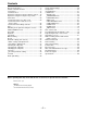
Contents General and Features ...............................................4 Controls and their functions ...................................... 6 • Front panel .............................................................. 6 • Connector area .....................................................15 Operations using the front panel bottom controls ....18 Operations using the front panel top controls ..........21 Connections .............................................................
General and Features This unit is a DVCPRO HD format HD digital video cassette recorder which is designed to use 1/4-inch wide compact cassette tapes. It is a studio-use digital VTR which can record, play back and edit HD signals (1080i, 59.94 Hz/60 Hz), and can play back tapes recorded using the existing DVCPRO (25 Mbps/50 Mbps) format. Use of the HD-SD conversion facility of the optional format converter enables interfacing with existing SD systems and development into HD systems.
General and Features Features (continued) Time codes This unit comes with a built-in time code generator (TCG)/time code reader (TCR). In addition to the internal time code, an external time code can also be recorded as the LTC on the unit’s tape.
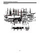
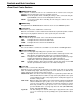
Controls and their functions Front panel 2 1 K F 9 GHI J Y 3 5 6 7 8 XZ 4 : EJECT M-cassette / ADAPTER ON Caution: Do not insert S-cassette without adapter ; OFF CH CONDITION ENTER ESCAPE L M N O SHIFT POWER [ ` _ TC MODE CONTROL TAPE REMOTE PUSH JOG UB TC/CTL L MONITOR SELECT SHIFT CH CH 1/5 CH 2/6 CH 3/7 CH 4/8 1 CH 4 5 CH CH 1 2 3 4 REC PULL OPEN PREVIEW REVIEW CH3/7 CH4/8 5 6 AUTO EDIT ADJ PLAYER RECORDER CUE 7 SERVO TC REC INHIBIT EDIT PLAY RE
Controls and their functions 1 POWER switch 2 TV system/format displays This shows the format during playback. HD: This indicates that the tape is recorded or played back in the DVCPRO HD format. 50 M: This indicates that the tape is played back in the DVCPRO (50 Mbps) format. 25 M: This indicates that the tape is played back in the DV or DVCAM mode of the DVCPRO (25 Mbps) format.
Controls and their functions < PLAY button Playback commences when this button is pressed. Recording commences when the button is pressed together with the REC button; manual editing commences when it is pressed together with the EDIT button during playback. However, manual editing will not be initiated if the servo is not locked. Pressing only the PLAY button during manual editing will cut out the editing and establish the playback mode.
Controls and their functions D STAND BY button When this is pressed, the same tension as in the regular stop mode is applied to the tape, and while the head drum continues to rotate, the button’s lamp lights to indicate that the standby ON mode is established. In the standby OFF mode, the half-loading mode is established. When this button is pressed in the stop mode, the standby OFF mode is established, the half-loading mode is established. The lamp in the button now goes off.
Controls and their functions J REMOTE/LOCAL switch This switch is set when the unit is to be controlled from an external source using the REMOTE connector, RS-232C connector or parallel connector. REMOTE: Set to this position when controlling the unit by a device connected using the 9-pin REMOTE connector or RS-232C/parallel connector. LOCAL: Set to this position when controlling the unit using the controls on its own operation panel.
Controls and their functions Q PREROLL button This is used for feeding and cueing the tape for manual editing. When it is pressed, the tape travels to the preroll point where it stops. The preroll time can be set on the setup menu No. 000 (P-ROLL TIME). When this button is pressed together with the IN or OUT button, the tape can be cued to the IN or OUT point entered. When the AUTO ENTRY on the setup menu No.
Controls and their functions X Counter display area The TC and CTL count values, UB and messages are displayed in this area. Cassette inserted display lamp: This lamp lights when a cassette has been inserted into the unit. DVCPRO format (25 Mbps/50 Mbps) cassette play display lamp: This lights when a cassette which was recorded using the DVCPRO (25 Mbps/50 Mbps) format is being played back. SCH lamp: This lights when the SCH phase of the SD REF signal is within a fixed range.
Controls and their functions ] Headphones jack The sound being recorded, played back or edited can be monitored on stereo headphones when they are connected to this jack. ^ Volume control This is used to adjust the headphones volume and the monitor output volume. Whether the headphones output and monitor output volumes are to be linked or kept separate can be set on the setup menu No. 713 (MONI OUT). (Note that the headphones output volume is normally linked.
Controls and their functions e SET button When this is pressed, the data which has been set on the setup menu is entered. After data entry, the setup menu setting mode is exited and the original operating mode is restored. f DIAG button When this is pressed, VTR information is displayed on-screen. When it is pressed again, the original display is restored. There are two types of VTR information: “HOURS METER” information and “WARNING” information.
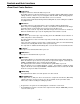
Controls and their functions Connector area > 6 5 7 89 = < 4 TC IN PUSH CUE IN PUSH SD SDISD SDI HD SDI MON L D OUT 1 OUT 2 4 OPTION OUT 3 (SUPER) IN OUT CH 1 PUSH OUT OUT 1 AUDIO IN CH1·2 CH3·4 CH5·6 CH7·8 AUDIO OUT CH1·2 CH3·4 CH5·6 CH7·8 R CH 2 PUSH AUDIO IN CH 3 PUSH IN (OPTION) OUT 2 OUT OUT 3 HD SDTI (SUPER) CH 4 PUSH VIDEO OUT 1 DIGITAL AUDIO ANALOG SD REF IN HD REF IN PARALLEL ON AC IN FUSE 125V 5A CH 1 CH 2 AUDIO OUT CH 3 CH 4 OFF ENCODER REMOTE ON
Controls and their functions 5 TIME CODE IN connector This is the connector for recording the external time code on the tape. 6 TIME CODE OUT connector The playback time code is output from this connector during playback. During recording, the time code generated by the internal time code generator is output. 7 CUE IN connector The analog signal to be recorded on the CUE track is supplied to this connector.
Controls and their functions @ SD REF IN connectors and 75-ohm termination switch These are the input connectors for the SD reference video signals. Input the NTSC signals with color burst. To terminate, set the switch to ON. A HD REF IN connectors and 75-ohm termination switch This is the input connectors for the HD reference video signals. Input tri-level sync signals with positive and negative polarities. To terminate, set the switch to ON.
Operations using the front panel bottom controls The desired status information and setup menu items can registered in the STATUS 1 to 3 buttons b and PROG MENU 1 to 4 buttons c by using the SETUP, STATUS, PROG MENU and SAVE/EXIT buttons a. Once the information has been registered, it can be indicated on the VTR status display area 3 by pressing the STATUS 1 to 3 buttons b or PROG MENU 1 to 4 buttons c concerned.
Operations using the front panel bottom controls 3 Turn the search dial and select the item to be registered. The cursor (¢) on the menu screen now moves. ∫Example of the menu displayed for registering setup menu items ASSIGN-MENU BASIC N0.000 - 1--¢000 P-ROLL TIME 1--001 LOCAL ENA -2-002 TAPE TIMER --3003 REMAIN SEL ---004 SYNCHRONIZE ---005 SUPER ---006 DISPLAY SEL ---007 CHARA H-POS ---008 CHARA V-POS ---- ∫Example of the menu displayed for registering VTR statuses ASSIGN-MENU N0.
Operations using the front panel bottom controls ∫To return the registered information to the factory settings (initial settings), press the RESET button while the registered menu item is displayed. The following message will appear.
Operations using the front panel top controls What has been registered in the STATUS 1 to 3 buttons b and PROG MENU 1 to 4 buttons c located at the bottom of the panel can be called to the VTR status display area 3 by pressing the button concerned. The called item can be operated using the buttons shown below.
Operations using the front panel top controls 2-2 How to change a registered menu setting Selecting the menu item: Press the SCROLL buttons 5 to move the item selection cursor (¢) up or down, and select the menu item. Transferring to the change mode: Press the ENTER button 6 to transfer to the setting change mode. Whether operation has transferred to the change mode is confirmed by the movement of the item selection marker to digit 14. Changing the setting: Press the scroll buttons 5 to change the setting.
Operations using the front panel top controls VTR status item table Name of registration menu item Item as it appears on VTR status display Description of display 000 REC FORMAT REC FMT This indicates the recording format. 1080i: The tape is recorded using the 1080i format. 001 REF OUT REFOUT This displays the output reference status. HD_59: The HD REF input signal has been selected as the reference. The field frequency is 59.94 Hz.
Connections Connections when one unit is used Set the CONTROL switch on the front panel to LOCAL.
Connections Connections when 2 units are used (deck to deck) • • Source machine: Recorder: Set the CONTROL switch on the front panel to REMOTE. Set the CONTROL switch on the front panel to LOCAL.
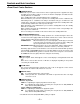
Connections Connections with editing controller Recorder AV monitor EJECT M-cassette / ADAPTER ON Video monitor signals Caution: Do not insert S-cassette without adapter OFF CH CONDITION ENTER ESCAPE SHIFT POWER TC TC INT UB EXT MODE TAPE CONTROL REMOTE PUSH JOG RESET METER TC/CTL L MONITOR SELECT SHIFT CH CH 4/8 5 CH ASMBL VIDEO CH1/5 CH2/8 CUE 1 2 3 4 PREVIEW REVIEW AUTO EDIT CH3/7 CH4/8 5 6 CUE 7 SERVO TC REC INHIBIT EDIT PLAY REC REW STOP FF 8 A PREROLL
Tapes Type Description Consumer cassette (S size cassette) Tapes with a maximum playback time of maximum of 33 minutes. (AJ-5P23MP, AJ-5P33MP) M size cassette DVCPROHD (100 Mbps) L size cassette These tapes are exclusively used with general consumer camera/recorder. They can be played back on the unit if a cassette adapter AJ-CS750P available as an optional accessory) is used. However, bear in mind that long-playing cassette tapes (80 minutes in the stadard mode; 120 minutes in the LP mode.
Switching on the power/inserting the cassette Before starting to operate the unit, check whether the equipment has been connected properly. 1 2 3 4 Turn on the power. Check that the AUTO OFF lamp is off. When condensation has formed or some other trouble has occurred, the AUTO OFF lamp lights, and all operations are disabled. Insert the cassette tape. Insert the tape at its proper position without force. Check that the STOP lamp is on.
STOP/STAND BY mode 1 2 When the STOP button is pressed, the unit goes into the stop mode. The STOP lamp lights and the tape stops traveling. • In order to protect the tape, the unit goes into the standby OFF mode after the time set by setup menu No. 400 (STILL TIMER) has elapsed. When the STOP, REW, FF or PLAY button is pressed, the unit will go into the appropriate mode. When the STAND BY button is pressed, the unit goes into the standby ON/OFF mode.
Recording 1 2 3 4 5 6 7 Set the accidental erasure prevention tab on the cassette tape to the “recording” position and insert the tape. Press the STOP button to place the unit in the stop mode. Set the TAPE/EE switch to EE. EE images now appear on the TV monitor. Check that the REC INHIBIT lamp is off. If this lamp is lighted, set the REC INHIBIT switch to OFF. Select the video and audio input signals and adjust their levels. 5-1 Selecting video/audio input signals 1 Connect the signals to be recorded.
Playback 1 2 3 4 Insert the cassette tape, and place the unit in the stop mode. Press the PLAY button. Regular playback is now commenced. Adjust the audio playback level. Pull out the audio level controls and turn them clockwise or counterclockwise to adjust the levels. Normally, they are kept in the pushed-in state (unity value). To end playback, press the STOP button. The VTR now goes into the stop mode. • Check that the SERVO lamp is lighted during playback.
Jog/shuttle Jog mode 1 2 3 Shuttle mode 1 2 3 4 Push the search dial to the “in” position. Be sure that the JOG lamp lights. Rotate the search dial. The dial’s clickstops are cleared, and the tape is played back at the speed (–1× to +1× normal speed) corresponding to the speed at which the dial is turned. When the dial rotation is stopped, a still picture appears. The playback picture is noise-free. To transfer from the jog mode to another mode, press the appropriate button.
Manual editing 1 2 3 4 5 Select the editing mode. ASSEMBLE: For assemble editing. INSERT: For insert editing. Select the editing channel. In the case of insert editing, press the channel button corresponding to the signals to be edited, and check that its lamp is on. Press the PLAY button. Search for the position where the editing is to be commenced (IN point) while viewing the TV monitor, and press the PLAY and EDIT buttons together at the IN point.
Preroll 1 Press the PREROLL button. The VTR now performs the preroll operation. • When the edit IN point has been entered, the tape is rewound from the edit IN point for the duration set by setup menu “000,” and the unit then goes into the stop mode. • When the edit IN point has not been entered, the tape is rewound for the duration set by setup menu “000” from the position where the button was pressed, and the unit then goes into the stop mode.
Automatic editing (Deck to Deck) Editing refers to the job of using a prerecorded tape to produce a complete recording by joining together separate cuts and deleting unnecessary parts. The basic steps taken for editing are as follows. 1 2 3 4 Set the CONTROL switch to REMOTE on the player and to LOCAL on the recorder. Select the editing mode. Enter the edit points of the recorder and player. Check and modify the edit points. 5 Check (Preview) before proceeding with the editing.
Automatic editing Switch settings and adjustments When the unit is used as the recorder: Set the CONTROL switch to LOCAL. Set the POWER switch to ON.
Automatic editing Selecting the editing mode 1 2 3 Select the editing mode. For assemble editing, press the ASMBL button. For insert editing, press the INSERT button. ASSEMBLE: The assemble editing mode (in which cuts are joined together) is established. INSERT: The insert editing mode (in which cuts are inserted) is established. Select the editing channel. With assemble editing, the ASMBL lamp lights.
Automatic editing Entering the edit points 1 2 3 4 Search for the edit IN point by performing the jog or shuttle operation. Establish the still picture mode at the desired position. Refer to page 32 for details on the jog/shuttle operations. Press the IN and SET buttons together. The edit IN point is now entered. The edit IN point value now appears on the display. Search for the edit OUT point by performing the jog or shuttle operation. Establish the still picture mode at the desired position.
Automatic editing Checking the edit points 1 2 3 Press the IN (or OUT) button to check the edit point. The value of the entered edit point appears on the display. Press the PREROLL button while holding down the IN (or OUT) button to check the image at the edit point. The tape is cued at the edit IN (or OUT) point, and the still picture mode at that point is displayed. • The EE mode is established if the TAPE/EE switch has been set to the “EE” position when “STOP” has been selected for the setup menu No.
Automatic editing Modifying the edit points 1 2 3 Re-entering the edit points Search for the new edit point by performing the jog or shuttle operation, and press the IN (or OUT) and SET buttons together to re-enter the edit point. Modifying the edit point in frame units (trim function) Press the TRIM button while holding down the IN (or OUT) button. The edit point is put ahead by 1 frame each time the + button is pressed. The edit point is put back by 1 frame each time the – button is pressed.
Automatic editing Preview 1 After the edit points have been entered, press the PREVIEW button. Normal preview is now performed. • If the edit IN point has not been entered, the position where the PREVIEW button was pressed will be entered at the edit IN point. • To stop the preview at any time, press the STOP button. • If the PREVIEW button is pressed again while preview is in progress after the IN point, preview will start again from the beginning.
Automatic editing Executing automatic editing 1 Press the AUTO EDIT button. Automatic editing is now performed. • To stop the editing at any time, press the STOP button. • When the edit OUT point is reached, the unit goes into the stop mode after postrolling. Postroll With assemble editing, editing continues for approx. 2 seconds even after the edit OUT point has been passed, the tape is rewound to the OUT point, and the unit goes into the stop mode.
Automatic editing Review 1 Upon completion of the editing, press the REVIEW button. The review is started in the recorder. • To stop the review at any time, press the STOP button. • When the edit OUT point is reached, the unit goes into the stop mode after postrolling.
Audio split editing The video edit points and audio edit points can be entered separately, and they can be offset from each other and edited. The audio edit points cannot be entered when the assemble editing mode has been selected. After the edit points have been entered, follow the same operating procedure as that for insert editing. ■ Entering the edit points Video IN point: Video OUT point: Audio IN point: Audio OUT point: Press the SET button while holding down the IN button.
Audio split editing ■ Displaying the audio split edit points The edit points are displayed on the front panel as shown below. (The figure shows an audio IN point.) Operations Video IN point: Video OUT point: Audio IN point: Audio OUT point: Press the IN button. Press the OUT button. Press the A-IN button. Press the A-OUT button. If the editing mode is switched to assemble editing after audio edit points have entered, these points will be deleted.
Setup (default settings) The unit’s major settings are performed by making selections on menus. The setting menus appear on the TV monitor when the TV monitor and VIDEO OUT 3 connector in the unit’s connector area are hooked up. Changing the settings 1 2 3 4 5 6 Press the MENU button. The setup menu appears on the TV monitor and setup menu No. appears on the counter display. (If the setup has already been performed, the screen showing the changes made last will appear.
Setup menus This unit can store up to 5 user files (user 1 to user 5) containing different menu settings, and these files can be selected and used. Changing the file 1 2 Press the MENU button. Hold down the STAND BY button and press the FF button to switch to the next user file. Hold down the STAND BY button and press the REW button to switch to the previous user file.
Setup menus Lock mode can be set to protect the settings in the system files and user files (USER2 – USER5). Settings can no longer be changed when this mode is set. To set and release the lock mode for the system files and user files use setup item No. 30 (MENU LOCK) and setup menu item No. A03 (MENU LOCK), respectively. Setting and releasing the lock mode. 1 2 3 4 Press the MENU button.
Setup menus The contents of the USER2 – USER5 files can be copied (loaded) into the USER1 file. In addition, the contents of the USER1 file can be copied (saved) to the USER2 – USER5 files. Load or save USER1 Load or save Load or save Load or save USER2 Settings can be locked. USER3 Settings can be locked. USER4 Settings can be locked. USER5 Settings can be locked. Loading a user file 1 2 3 Press the MENU button.
Setup menus Saving a user file 1 2 3 Press the MENU button. While holding down the STAND BY button, press the REW or FF button, and select USER1. Turn the search dial and move the cursor (¢) on the menu screen to setup item No. A01 (SAVE). SETUP-MENU MENU NO.A00 - 0000 759 REC PT MUTE OFF A00 LOAD USER2 ¢A01 SAVE USER2 A02 P.ON LOAD OFF END 4 5 While holding down the search button, turn the search dial and select the user file into which the USER1 contents are to be saved.
Setup menus SYSTEM menu Item Setting Description No. Superimposed display 00 WFM SEL 0000 0001 0002 0003 0004 0005 0006 0007 CTL TC VIDEO SYNC RF-L RF-R ENV-L ENV-R This selects the signal to output from the VIDEO OUT 2 connector. 0: The CTL signal is output. 1: The TIME CODE signal is output. 2: The VIDEO OUT signal is output. 3: The SYNC signal is output. 4: The PB L RF signal is output. 5: The PB R RF signal is output. 6: The PB L ENV signal is output. 7: The PB R ENV signal is output.
Setup menus SYSTEM menu (continued) Item No. Setting Superimposed display No. Description Superimposed display 15 VO SYS H (SD)*1 0000 : 0429 : 0858 –429 : 0 : 429 This enables the system phase to be adjusted in 74ns steps. -: The phase is advanced. +: The phase is delayed. If setting operation is performed, the setting value does not return to factory (default) setting.
Setup menus USER menu Item No. Superimposed display Setting No. Description Superimposed display 000 P-ROLL TIME 0000 : 0005 : 0015 0S : 5S : 15S This sets the preroll time which can be set from 0 to 15 seconds in 1-second increments. When the unit is set to automatic editing [PREVIEW, AUTO EDIT], the unit will not operate if the preroll time is set to 0 seconds.
Setup menus USER menu (continued) Item No. Superimposed display Setting No. 006 DISPLAY SEL 0000 0001 0002 007 CHARA H-POS 0000 : 0006 : 0037 008 CHARA V-POS Description Superimposed display TIME T&STA T&S&M This selects what displays such as the time code are to be superimposed onto the HD SDI OUT3, SD SDI OUT3 and VIDEO OUT3 connector signals. 0: Time only 1: Time and operation mode 2: Time, operation mode and mode 1.
Setup menus USER menu (continued) Item Setting Description No. Superimposed display 022 PB FORMAT 0000 0001 0002 0003 0004 1080I 422 411 DV DVCAM This selects the playback tape format. 0: For playing back a 1080i mode tape. 1: For playing back a DVCPRO50 422 mode tape. 2: For playing back a DVCPRO 411 mode tape. 3: For playing back a DV tape. 4: For playing back a DVCAM tape. Before the PB FORMAT menu item setting is to be changed, eject the tape first and then proceed.
Setup menus USER menu Item Setting Description Superimposed display No. 100 SEARCH ENA 0000 0001 DIAL KEY This selects the direct search dial operation. 0: For direct search dial operations. 1: Operation is not transferred to the search mode unless the search button is pressed. 101 SHTL MAX 0000 0001 0002 ×8.4 ×16 ×32 This sets the maximum speed for shuttle operations. 0: 8.4× normal speed 1: 16× normal speed 2: 32× normal speed 102 FF.
Setup menus USER menu (continued) Item Setting Description Superimposed display No. 107 EE MODE SEL 0000 0001 NORMAL THRU 108 PLAY DELAY 0000 : 0015 0 : 15 This set the play delay time in frame increments. 109 CAP.LOCK 0000 0001 2F 4F This selects whether the playback framing is to be locked in 4field or 2-field increments.
Setup menus USER menu (continued) Item Setting Description No. Superimposed display 113 REC INH 0000 0001 OFF ON This selects whether to allow or inhibit recording on the cassette tape. 0: Recording on the tape is allowed when its accidental erasure prevention tab has been set to the recording enable position. 1: Recording on the tape is inhibited.
Setup menus USER menu Item Setting Description No. Superimposed display 200 PARA RUN 0000 0001 DIS ENA This selects whether two or more VTRs are to be operated in synchronization. 0: No operation in synchronization 1: Operation in synchronization When operating two or more VTRs in synchronization, set all the VTRs to 0001 (ENA). 201 9P SEL 0000 0001 OFF ON This selects whether the 9P connector functions when the REMOTE/LOCAL switch has been set to REMOTE.
Setup menus USER menu (continued) Item Setting Description No. Superimposed display 211 LOCAL 50P 0000 0001 OFF ON This selects whether the PARALLEL (50P) connector is to work when the REMOTE/LOCAL switch has been set to LOCAL. 0: The connector does not work. 1: The connector works. 212 MASTER PORT 0000 0001 IN/OUT OUT This selects the remote control connector for controlling the slave machine when the unit is to be used as the master machine for deck-to-deck operations.
Setup menus USER menu Item Setting Description Superimposed display No. 300 IN/OUT DEL 0000 0001 MANU AUTO This selects the operation to be performed when an edit point has been set incorrectly (when the OUT point is before the IN point). 0: Editing is not executed unless the illegal edit point is cleared or set again properly. 1: The edit points already input are automatically cleared.
Setup menus USER menu (continued) Item No. Superimposed display Setting No. Description Superimposed display This sets the maximum JOG REV speed. 0: –4.1× speed 1: –1.85× speed 2: –1× speed 3: –0.43× speed • The maximum speed is set to –1× when the dial on the front panel is operated. • At any speed setting other than 1 (–4.1×), the phase cannot be synchronized from an editing controller which synchronizes the phase using the JOG command. 311 JOG REV MAX 0000 0001 0002 0003 –4.1 –1.
Setup menus USER menu (continued) Item No. 324 Superimposed display EDIT RPLCEC Setting No. 0000 0001 0002 0003 Description Superimposed display N-DEF CH1 CH2 CH1+2 The same type of setting as setup menu No. 320. This selects the channel concerned when the CUE edit preset is set in compliance with the ON or OFF presetting for the analog audio signals designated by the editor or controller. 0: Not set. 1: Compliance with analog CH1 edit preset. 2: Compliance with analog CH2 edit preset.
Setup menus USER menu Item No. Superimposed display Setting No. Description Superimposed display 400 STILL TIMER 0000 0001 0002 0003 0004 0005 0006 0007 0008 0.5s 5s 10s 20s 30s 40s 50s 1min 2min This selects the time to be taken until the unit goes into the tape protection mode when it is left standing in the stop or search still (JOG/VAR/SHTL) mode.
Setup menus USER menu
Setup menus USER menu
Setup menus USER menu
Setup menus USER menu
Setup menus USER menu
Setup menus USER menu
Setup menus USER menu
Setup menus USER menu
Setup menus USER menu
Setup menus USER menu
Setup menus USER menu
Setup menus USER menu
Setup menus USER menu
Time code/user bit Time code The time code is used when the time code signal generated by the time code generator (time code signal generator) is to be recorded on the tape, its values are to be read by the time code reader (time code signal reader), and the absolute position of the tape is to be displayed in increments of hours, minutes, seconds and frames. The time code is written in the sub-code area (data area) of the helical track.
Recording internal/external time codes 1. Setting the internal time code 1 2 3 4 5 6 Place the VTR in the stop mode. Set the TC/CTL switch to TC. Set the TC INT/EXT switch to INT. (Internal time code selected) Set the Setup menu No. 504 (RUN MODE). REC RUN: The time code runs at the same time as the recording proceeds. FREE RUN: The time code runs in the same way as the time regardless of the VTR’s operation. Set the Setup menu No. 503 (REGEN).
Reproducing the time code/user bit 1 2 3 4 Place the unit in the stop mode. Set the TC/CTL button to TC. Set the TC/UB switch to TC or UB. TC: The time code is displayed. UB: The user bit is displayed. • When it is no longer possible to read the time code, it is interpolated using the CTL signal. Press the PLAY button. Playback now commences, and the time code appears on the display. When setup menu No.
Superimpose screen The control signals, time code, etc. are displayed using abbreviations. CTL = control signal TCR = TC time code reading UBR = TC user bit reading Abbreviation TCR : : : TV monitor Characters displayed The background of characters superimposed on the display can be changed using setup menu No. 009 (CHARA TYPE). TCR : : : TV monitor Display position The position of the characters superimposed on the display can be changed using setup menus No. 007 (CHARA H-POS) and No.
Audio recording channel and monitor output selection Audio recording channel The audio recording channels are selected on the AUDIO setup menu as shown below.
Printed circuit board Printed circuit board F1 board ADDA Abbr. name SW1 Function Factory setting Audio Input Impedance SW This sets the CH1 audio input impedance. HIGH/600Ω HIGH Audio Input Impedance SW This sets the CH2 audio input impedance. HIGH/600Ω HIGH SW 201 Audio Input Impedance SW This sets the CH3 audio input impedance. HIGH/600Ω HIGH SW 301 Audio Input Impedance SW This sets the CH4 audio input impedance. HIGH/600Ω HIGH SW101 This sets the CUE input impedance.
Rack mounting The unit can be mounted into a 19-inch standard rack if the optional rack-mounting adapters (AJ-MA75P) are used. For the installation rails, it is recommended that the rail and bracket for 18q length (model number CC3061-99-0400) of Chassis Trak be used. If an even greater clearance is to be left between the VTR and rack when the VTR is pulled out, however, it is recommended that the 22q long Chassis Trak (model number CC-3001-99-0191) be used.
Video head cleaning This unit is equipped with an auto head cleaning function which automatically reduces the amount of dirt on the video heads. In order to maximize the unit’s reliability, it is recommended that the video heads be cleaned as and when appropriate. For further details on how to actually clean the heads, consult with one of our service companies or with your dealer.
Error messages When a warning occurs in this unit, the warning lamp lights up. Opening the DIAG menu will display the warning description on the counter display and the monitor. Also, when an abnormal operation is detected in this unit, the AUTO OFF lamp lights up and a message appears on the counter display. DIAG menu This display the VTR information. VTR information includes “WARNING” information and “HOURS METER” (usage time) information.
Error messages Displaying the “HOURS METER” information Turn the search dial to move the cursor ( * ). The description for the item where the cursor is located is shown on the counter display. Item No. Item Description H00 OPERATION Displays the time that the power has been supplied in one-hour units. H01 DRUM RUN Displays the time that the drum has been rotating in one-hour units.
Table of AUTO OFF Error messages Counter display Monitor display Description VTR operation (Restart condition) CAP ROTATE TOO SLOW CAP ROTA TOO SLOW If the capstan motor speed is abnormally low, the STOP AUTO OFF lamp lights, and the message display (POWER OFF→ON) flashes. CAP TENSION ERROR CAP TENSION ERROR If an abnormal tension at the supply side is detected STOP in the capstan mode, the AUTO OFF lamp lights, and (POWER OFF→ON) the message display flashes.
Table of AUTO OFF Error messages Description VTR operation (Restart condition) Counter display Monitor display REEL DIR UNMATCH REEL DIR UNMATCH REEL TENSION ERROR REEL TENSION ERROR If an abnormal tension at the supply side is detected STOP in the reel mode, the AUTO OFF lamp lights, and the (POWER OFF→ON) message display flashes.
RS-232C interface 1. Introduction (1) The VTR can be operated by commands when the RS-232C interface is used. (See command table on page 93 – 95.) (2) Conditions for acknowledging commands from RS-232C interface The front panel REMOTE/LOCAL switch must be at REMOTE. The setup menu item No. 204 “RS232C SEL” must be ON. If the above conditions are not met, [ACK] + [STX]ER001[EXT] is returned to the external unit.
RS-232C interface 3. Software specifications Protocol 1) Communication parameters Communication system Asynchronous, full duplex Communication speed 300/600/1200/2400/4800/9600 Bit length 7 bit/8 bit Stop bit 1 bit/2 bit Parity bit NONE/ODD/EVEN ACK code ACK code returned/ACK code not returned The ACK code is what is returned from the VTR to the controller when data has been successfully sent from the controller. The underlining indicates the factory settings.
RS-232C interface 3) Return format [VTR → controller (PC)] The following responses are made to the command. If necessary, more than one response is made. ■ When the communication has terminated normally 1. The receive completion message is returned. [ACK] 06h 2. The execution completion message is returned. [STX] [command] [data] [ETX] 02h XX XX XX XX-XX 03h • [command]: This is the message (data) which is returned or the execution completion message identifier. This is the data to be returned.
RS-232C interface 5. Command table (1) Commands relating to operation control • As for the return (completion) message, [ACK] is first returned when data is received, and the execution message is subsequently returned. It is only the execution message which is listed in this table. • In the case of commands not listed in the table, ER001 (invalid command) is returned after [ACK] has been returned.
RS-232C interface VTR operation SHTL REVERSE Send command Return (completion) message [STX] OSR:data [ETX] [STX] OSR [ETX] Supplementary notes This is the reverse direction shuttle command. speed data STILL ×0.03 ×0.1 ×0.2 ×0.5 ×1 ×1.85 ×4.1 ×9.5 ×16 : This speed differs according to the setting selected for setup menu No. 101 (SHTL MAX). A: ×32 : This speed differs according to the setting selected for setup menu No. 101 (SHTL MAX).
RS-232C interface (2) Commands relating to inquiries • As for the return (completion) message, [ACK] is first returned when data is received, and the execution message is subsequently returned. It is only the execution message which is listed in this table. • In the case of commands not listed in the table, ER001 (invalid command) is returned after [ACK] has been returned.
RS-232C interface (3) Microsoft QuickBASIC sample program CLS STX$ = CHR$(&H2): ETX$ = CHR$ (&H3): NAK$ = CHR$(15): ACK$ = CHR$(&H6) PRINT "*** RS-232C COMMUNICATION SAMPLE PROGRAM ***" PRINT "Type Command 'QUIT' to quit.
Connector signals VIDEO IN HD SERIAL IN (DIGITAL) BNC × 2 Active through HD SDTI IN BNC × 2 Loop-through, 75Ω termination switch provided VIDEO IN BNC × 2 Loop-through, 75Ω termination switch provided HD SDTI IN BNC × 1 (Board, option) VIDEO OUT HD SERIAL OUT (DIGITAL) BNC × 3 SD SERIAL OUT (DIGITAL) BNC × 3 VIDEO OUT BNC × 3 HD REF OUT BNC × 1 SD REF OUT BNC × 1 SERIAL IN (DIGITAL) BNC × 2 Active through AUDIO IN (DIGITAL) XLR × 4 CH1/CH2,CH3/CH4,CH5/CH6, CH7/CH8 AES/EBU format AUDI
Connector signals PARALLEL REMOTE (50P) Pin No. Signal Pin No. Signal Pin No.
Specifications GENERAL Power supply: AC 120 V, 50 – 60 Hz Power consumption: 230 W Operating ambient temperature: Operating ambient humidity: Weight: Dimensions (W × H × D): Recording format: Recording video signal: Recording audio signal: Recording tracks: Tape speed: Recording time: Tape: FF/REW time: Search speed: Digital slow: Editing accuracy: Tape timer accuracy: Servo lock time: Loading time: Audio split editing: 41°F to 104°F (5°C to 40°C) 10% to 90% (no condensation) 44 lbs (20 kg) 16-3/4" (max.
Specifications HD SDI output system phase: SD SDI Y output gain: SD SDI PB output gain: SD SDI PR output gain: SD SDI Y black level: SD SDI output system phase: Composite video output gain: Composite chroma output gain: Composite chroma phase: Composite video output setup: Composite video output system phase: Composite video output SC phase: SD SDI and composite output video phase: HD SDI output video phase: ±0.5H (1100 samples, 13.5 ns steps) –¶ to +3 dB –¶ to +3 dB –¶ to +3 dB ±10% ±0.
– 101 –
PANASONIC BROADCAST & DIGITAL SYSTEMS COMPANY DIVISION OF MATSUSHITA ELECTRIC CORPORATION OF AMERICA Executive Office: 3330 Cahuenga Blvd W.