Camera/VTR AJ- P Operating Instructions
FCC Note: This device complies with Part 15 of the FCC Rules. To assure continued compliance follow the attached installation instructions and do not make any unauthorized modifications. CAUTION RISK OF ELECTRIC SHOCK DO NOT OPEN CAUTION: TO REDUCE THE RISK OF ELECTRIC SHOCK, DO NOT REMOVE COVER (OR BACK). NO USER SERVICEABLE PARTS INSIDE. REFER TO SERVICING TO QUALIFIED SERVICE PERSONNEL.
Contents Introduction . . . . . . . . . . . . . . . . . . . . . . . . . . . . . . .5 Features . . . . . . . . . . . . . . . . . . . . . . . . . . . . . . . . . .5 Features of the camera unit . . . . . . . . . . . . . . . . . .5 Features of the VTR unit . . . . . . . . . . . . . . . . . . . .7 System configuration . . . . . . . . . . . . . . . . . . . . . . .8 Parts and their functions . . . . . . . . . . . . . . . . . . . .9 Power supply section . . . . . . . . . . . . . . . . . . . . . . .
Contents Setting menu screens . . . . . . . . . . . . . . . . . . . . . .77 CAM MAIN MENU 1 screen . . . . . . . . . . . . . . . . .77 CAM MAIN MENU 2 screen . . . . . . . . . . . . . . . . .77 CAM MAIN MENU 3 screen . . . . . . . . . . . . . . . . .77 CAM MAIN MENU 4 screen . . . . . . . . . . . . . . . . .77 CAM MAIN MENU 1 ROP screen . . . . . . . . . . . . . . . . . . . . . . . . . . . . .78 MATRIX screen . . . . . . . . . . . . . . . . . . . . . . . . . .78 COLOR CORRECTION 1 screen . . . .
Introduction The AJ-HDC20A integrates two units: 1) a highdefinition (HD) color video camera featuring an FITCCD equipped with a 2.2 million pixel on-chip lens that supports the full spectrum of HD TV (1080i/59.94 Hz), and 2) a DVCPRO HD format VTR that incorporates the latest compression technology.
Features Features of the camera unit Wide-ranging video gain selection A value ranging from –3 dB to +30 dB can be selected for the gain using the setting menu and GAIN switch. Even when the gain is increased for shooting in dark locations, images with minimal noise can be obtained because of the high signal-to-noise ratio. The super gain function can be allocated to the USER button, and 30 dB can be selected using this button.
Features Features of the VTR unit Digital system The pictures are compressed by a component digital recording system that uses the latest compression technology while non-compression PCM recording featuring excellent signal-to-noise ratio, frequency band, waveform characteristics and reproduction of detailed areas is employed for the sound. The result is an even higher picture and sound quality.
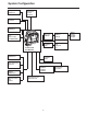
System Configuration Microphone kit AJ-MC700P Wireless microphone receiver WX-RJ700 2˝ viewfinder AJ-HVF20 Microphone holder AJ-MH700P Battery case AU-M402H Lens (Bayonet type) FUJINON/CANON Panasonic Battery AU-BP402 AJ-BP490 Anton/Bauer Battery Battery case/Battery holder Camera/VTR AJ-HDC20A Rain cover SHAN-RC700 Sony Battery BP-90 BP-L60/L90 NP-1 AC adapter AJ-B75 Soft carrying case AJ-SC900 Cassette tape AJ-HP23LP AJ-HP32LP AJ-HP46LP Tripod mount adapter SHAN-TM700 Extension control unit
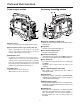
Parts and their functions Power supply section Accessory mounting section 1 2 1 5 6 3 4 1 6 9 4 8 2 7 3 1 Hooks for attaching shoulder strap Attach the ends of the accessory shoulder strap to these hooks. 1 Battery mount This is for attaching the Anton/Bauer battery pack. 2 Light shoe Use this to attach the video light, etc.
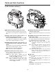
Parts and their functions Audio function section (1) 2 3 4 7 1 6 5 1 MIC IN (microphone input) jack (XLR, 3-pin) Connect the microphone (optional accessory) here. The power for the microphone is supplied from this jack. 5 AUDIO IN CH1/CH2 (audio input channel 1 & 2) connectors (XLR, 3-pin) An audio component or microphones are connected here.
Parts and their functions Audio function section (2) < Speaker The EE sound during recording or the playback sound during playback can be monitored through this speaker. The warning alarms are output in synchronization with the flashing or lighting of the warning lamps and warning displays. The sound heard from the speaker is automatically cut off when the earphone is connected to the PHONES jack ?.
Parts and their functions Viewfinder section (1) > <7 8 3 TALLY switch This is used to control the front tally lamp 7. HIGH : The brightness of the front tally lamp is increased. OFF : The front tally lamp is turned off. LOW : The brightness of the front tally lamp is reduced. 4 PEAKING control This is used to adjust the outlines of the images seen inside the viewfinder to make focusing easier. Its adjustment does not affect the output signals of the camera.
Parts and their functions Shooting (recording)/playback function section (1) $ Examples of filter selection CC filter Shooting conditions B Outdoors under a clear sky C (4300 K) or D (6300 K) 2 (1/4 ND) or 3 (1/16 ND) Outdoors under cloudy or rainy skies D 6300 K 1 (CLEAR) or 2 (1/4 ND) 3200 K 1 CC FILTER/ND FILTER (filter selector) control This is used to select the filter to match the light source which is illuminating the subject.
Parts and their functions Shooting (recording)/playback function section (2) 6 5 4 4 OUTPUT (output signal selector)/AUTO KNEE switch This is used to select the video signals which are to be output from the camera unit to the VTR unit, viewfinder and video monitor. The AUTO KNEE function can be used when the pictures shot by the camera are selected. 5 GAIN (gain selector) switch This is used to select the gain of the video amplifier in accordance with the lighting status during shooting.
Parts and their functions Shooting (recording)/playback function section (3) : 9 7 9 7 SHUTTER switch This is set to ON when the electronic shutter is to be used. When the SEL side is pressed, the shutter speed and mode display are changed in the range which was set ahead of time in the setting menu. If this switch setting is changed while the display mode is set to “2” or “3,” the new setting will appear at the shutter display position on the viewfinder screen. (Example: “: 1/120”, “: 1/61.
Parts and their functions Shooting (recording)/playback function section (4) < = ; ; CHARACTER switch This controls whether the characters are to be superimposed onto the pictures which are output from the HD SDI OUT connector. ON : The characters are superimposed. OFF : The characters are not superimposed. = VTR SAVE/STBY (tape protection) switch This is used to select the power supply mode when the VTR has temporarily stopped recording (REC PAUSE mode). SAVE: This is the tape protection mode.
Parts and their functions Shooting (recording)/playback function section (5) C @ A B D > E ? > MODE CHECK button While this button is held down, the camera’s setting mode is shown in the viewfinder. This does not affect the output signals of the camera. C PLAY/PAUSE button This is pressed to view the playback picture on the viewfinder screen or using a color video monitor. The button’s lamp comes on during playback.
Parts and their functions Warning/status display section 4 1 2 3 5 1 Back tally lamp (unit) When the back tally switch 2 is set to ON, this lamp serves the same function as the front tally lamp in the viewfinder. 2 Back tally switch This is used to control the unit’s back tally lamp 1. ON : The unit’s back tally lamp is operational. OFF : The unit’s back tally lamp is not operational. 3 WARNING lamp When a problem of some form or other occurs within the VTR unit, this lamp flashes or lights.
Parts and their functions Menu operation section 3 JOG dial button When this dial button is turned while the menu screen is displayed, the cursor is moved to each of the setting items. The menu items are set by operating this dial button. There are two types of menus, MAIN and SUB, and each menu is displayed on a page-by-page basis. The menu configuration can be changed to suit the desired objective. For details on the menu operation method, refer to “Menu operations” on pages 70 to 72.
Parts and their functions Time code related section (2) 46 5 9 8 7 4 HOLD button The time data display of the counter display section which was on the screen at the moment when this button is pressed is held. (However, the time code generator keeps running.) When the button is pressed again, the hold status is released. It is used, for instance, to find out the time at which a particular scene was shot.
Power supply A battery pack or an AC power source can be used as this unit’s power supply. Using the Anton/Bauer battery pack the battery pack. 1 Attach Insert the pack in the direction shown by the To use the battery pack, there is a choice of three makes of batteries, namely: OPanasonic OAnton/Bauer OSony arrows, and then slide it into position.
Power supply Using the Panasonic AU-BP402 battery pack 1 Detach the battery mount. the AU-M402H battery case. 3 Attach Open the battery case cover, and raise it above the rubber cap: screw holes will now be visible. Tighten the screws using a screwdriver, then attach the case to the unit and tighten the screws fully. the AU-M402H battery case connector 2 Connect with the connector on the unit. O Do not pull the rubber cap forcefully.
Power supply Using the Sony NP-1 battery pack Using the Sony BP-90 battery pack the battery mount. 1 Detach See page 22. 1 Attach the accessory battery mounting connector. 2 Attach the battery case for the BP-90. 2 Attach the accessory battery mounting connector. 1. Tighten the mounting screws. 2. Tighten the power contact screws. 3. Insert the top of the detached cover in the direction shown by the arrows. 4.
Power supply Using the Sony BP-L60/L90 lithiumion battery Using an AC power supply the accessory battery mounting connector. 1 Attach (Refer to the previous page.) the DC OUT connector on the AJ-B75 AC 1 Connect adapter to the EXT DC IN socket on the unit. When the AJ-B75 AC adapter is used 2 Attach the battery holder for the lithium-ion battery. 1. As shown in the figure, detach the battery clamp, and attach the holder using the mounting screws. 2. Tighten the power contact screws. 3.
Attaching the lens the lever for securing the lens, and detach the cable into the cable clamp, and connect it 1 Raise 4 Push the mount cap. to the LENS socket. Lever for securing the lens Mount cap LENS socket the center mark of the lens with the groove in 2 Align the top center of the lens mount, and attach the O For details on handling the lens, refer to the operating instructions which accompany the lens.
Adjusting the lens flange If the subject is not focused properly in the telephoto and wide-angle modes during zoom operations, adjust the flange back (distance from the lens mounting surface to the image-forming surface). Once this adjustment is done, it need not be redone unless the lens is replaced. Adjustment method For details on the adjustment method and lens positions, refer also to the operating instructions that accompany the lens. Approx. 3 meters the lens to the camera.
Adjusting the white shading the menu operations (pages 70 to 72), 4 1 Perform and display the “VF DISPLAY” screen of CAM Follow the procedure outlined below when the white shading needs to be re-adjusted. MAIN MENU 2. 2 Set ZEBRA1 DETECT to 70%, ZEBRA2 DETECT to 85% and ZEBRA2 to STOP. (Default setting mode) 3 Press the MENU button and close the menu screen. 4 Set the ZEBRA switch on the viewfinder to ON.
Adjusting the white shading If the lens is provided with an extender, engage the WHITE BAL selector switch to “A” or “B,” 7 1 Set 10 the extender function, and repeat steps 6 to 9. and initiate the automatic white balance (AWB) adjustment using the AUTO W/B BAL switch. 2 Initiate the automatic black balance (ABB) adjustment using the AUTO W/B BAL switch. 3 Initiate the automatic white balance (AWB) adjustment again using the AUTO W/B BAL switch. The white shading adjustment is now complete.
Adjusting the viewfinder (The viewfinder is an optional accessory.) Attaching the viewfinder Detaching the viewfinder 1 Check that the camera’s POWER switch is at OFF. 1 Check that the camera’s POWER switch is at OFF. the plug to the viewfinder connecting the stopper screw, pull the viewfinder 2 Connect 2 Loosen terminal. straight up, and draw it out. When connecting the plug to the viewfinder connecting terminal, push the plug firmly into place. Use both hands to draw the viewfinder out.
Adjusting the viewfinder (The viewfinder is an optional accessory.) Adjusting the viewfinder position up the lever for securing the viewfinder in the 1 Pull back/front and sideways directions to disengage the lock. Lever Viewfinder the lever for securing the viewfinder in the 2 Loosen back/front and sideways directions. the viewfinder in the back/front and sideways 3 Move directions, and adjust its position.
Audio input preparation When attaching a microphone to the viewfinder (optional accessory) for use The microphone of the AJ-MC700P mic kit (optional accessory) can be attached to the viewfinder. 1 Open the mic holder. the AUDIO IN switch or switches to “FRONT” 4 Set in accordance with the audio channel or channels AJ-HVF20 whose sound is to be recorded. Mic holder the microphone, and tighten the locking 2 Attach screw.
Audio input preparation When attaching a microphone to the main unit for use Attaching the AJ-MH700P mic holder (optional accessory) 1 Remove the screws used to attach the mic holder. the microphone’s connecting cable to the 4 Connect MIC IN jack on the camera. MIC IN jack the AUDIO IN switch or switches to “FRONT” 5 Set the mic holder to the main unit using the 2 Attach in accordance with the audio channel or channels screws provided with the AJ-MH700P mic holder. whose sound is to be recorded.
Audio input preparation When connecting a microphone to the MIC IN jack When connecting a microphone to the AUDIO IN connector the microphone’s connecting cable to the the microphone’s connecting cable to the 1 Connect 1 Connect MIC IN jack on the camera. AUDIO IN connector on the camera. Two microphones can be connected to the CH1 and CH2 connectors. MIC IN jack the AUDIO IN switch or switches to “FRONT” 2 Set in accordance with the audio channel or channels whose sound is to be recorded.
Audio input preparation When using a wireless microphone When connecting audio components Attach the WX-RJ700 wireless receiver when Panasonic’s wireless system is to be used. the AUDIO IN connectors on the camera 1 Connect with the audio component using the XLR cable. the WX-RJ700 wireless receiver to the WX1 Attach ZJ770 camera attachment. the grooves in the camera attachment with 2 Align the pins on the battery case, etc. to attach the wireless receiver.
Mounting the unit on a tripod Use the tripod attachment available as an optional accessory for mounting the unit onto a tripod. Detaching the unit from the tripod attachment While pressing the red lever, move the black lever in the direction of the arrow, slide the unit toward the rear, and detach it. the tripod attachment to the tripod. 1 Attach Tripod attachment Select the attachment holes that best support the center of gravity of the unit and tripod attachment.
Attaching the shoulder strap the shoulder strap to the shoulder strap 1 Attach mounting hooks, and adjust the length of the strap. To detach the shoulder strap, open the clips on the mounting parts and detach. Check that the shoulder strap is securely fastened. The clip opens when it is pressed here. Shoulder strap The clip opens when it is pressed here.
Attaching the rain cover Example showing use of the SHANRC700 rain cover Tighten the cord. Close using the fastener. Close using the fastener. Connecting the extension control unit By connecting the AJ-EC3 extension control unit (optional accessory), some of the functions can be operated by remote control. When the AJ-EC3 is connected and the POWER switches on the unit and AJ-EC3 are set to ON, the unit is automatically set to the remote control mode.
Viewfinder lamp displays 1 TALLY / REC BATT VTR SAVE 3 2 1 TALLY/REC (recording) lamp This lights up (red) during recording. It flashes when a problem has occurred. For details, refer to the section on the “Warning system” (pages 105, 106). 4 VTR SAVE (VTR power-saving) lamp This lights when the VTR SAVE/STBY switch is set to SAVE. It goes off during recording.
Viewfinder lamp displays Setting the lamp displays Select the items targeted for the lamp display on the “!LED” screen of the CAM MAIN MENU 2 screen. (Under the factory settings, the “!LED” screen is not displayed.) To perform operations on the “!LED” screen, either switch the unit to the engineer mode menu or select the “!LED” screen on the CAM USER MENU SELECT 2 screen under the CAM MAIN MENU 4 screen.
Viewfinder screen status displays In addition to the pictures shot, the unit’s settings and messages indicating its operating statuses are displayed on the viewfinder screen. The center marker and safety zone markers also appear. The items which have been set to ON by the switches relating to the viewfinder displays or the VF DISPLAY screen of the setting menu are displayed at the top and bottom of the screen.
Viewfinder screen status displays 1 Extender display This appears when the lens extender is being used. : Camera warning/information display The black balance, white balance, auto knee function, super iris, super gain and other alarm displays and warnings appear here. 2 Shutter speed/mode display This indicates the shutter speed or shutter mode setting. O OFF (no display): The shutter is not used. O 1/100, 1/120, 1/250 1/500, 1/1000, 1/2000: Shutter speeds (sec.) in the standard mode O 1/30.3 to 1/250.
Viewfinder screen status displays Selecting the display items The items to be displayed on the viewfinder screen can each be set to ON or OFF on the “VF INDICATOR” screen of the CAM MENU or on the “VTR VF INDICATOR” screen of the VTR MENU. Selecting the display items the menu operations (pages 70 to 72) to 1 Perform open the “VF INDICATOR” screen.
Viewfinder screen status displays Display modes and setting change messages The display of messages advising the user of what changes have been made to the settings and what the adjustment results are can be turned off for some or all of the items displayed.
Viewfinder screen status displays Switching the display mode Setting the camera ID The display mode settings are switched on the VF DISPLAY screen. The camera ID is set on the CAMERA ID screen. Up to ten alphanumerics, symbols and spaces can be used. The camera ID is not displayed while the setting menu is displayed even if color bar signals are output. the menu operations (pages 70 to 72) to 1 Perform open the “VF DISPLAY” screen.
Screen displays Remaining battery charge and audio channel level and remaining tape displays Displays relating to time codes These displays light for the time code, CTL and actual time DF : Drop frame mode SLAVE : External locking of the time code HOLD : Time code generator in the hold mode (when the HOLD button has been pressed) Remaining tape display When there are 21 or more minutes of the tape remaining, all 7 segments up to the “F” position light.
Adjusting the date and time Adjustments and setup using the setting menus the menu operations (pages 70 to 72), the 1 Perform 5 Press and display the “TIME/DATE” screen. operations. The setting menu is cleared, and the display showing the unit’s current statuses appears at the top and bottom of the viewfinder screen. n< TIME/DATE > YEAR MONTH DAY HOUR MINUTE :00 :01 :01 :00 :00 The seconds cannot be set. advances from 0 seconds.
Adjusting the white balance and black balance Adjusting the white balance 1 Set the switches as shown in the figure. A better picture can be achieved by adjusting the white balance and black balance in the following sequence: AWB (white balance adjustment) 5 ABB (black balance adjustment) 5 AWB. There is usually no need to re-adjust the black balance even when the power has been turned off and back on. The white balance must always be re-adjusted when the lighting conditions have changed.
Adjusting the white balance and black balance Adjusting the white balance a white pattern at a place with the same the adjustment is in progress, the following 3 Erect 6 While conditions as the source of light illuminating the message appears on the viewfinder screen (but subject, zoom in, and shoot the white of the pattern on the screen. A white object (such as a white cloth or white wall) near the subject may be used as a substitute for the white pattern.
Adjusting the white balance and black balance Adjusting the white balance When the white balance cannot automatically be adjusted When there is no time to adjust the white balance An error message appears on the viewfinder screen (when “2” or “3” has been set as the display mode). Set the WHITE BAL switch to PRST. The white balance for the filter is achieved in accordance with the setting position of the FILTER control (outer).
Adjusting the white balance and black balance Adjusting the white balance When FILTER INH is set to ON When AWB is adjusted, the color temperature and filter number applying at the time are displayed. If the filter is then turned, the color temperature and filter number are displayed. The white balance is almost fully adjusted if the subject is illuminated at a color temperature approaching the one displayed. (Example of display) AWB A OK 3.
Adjusting the white balance and black balance Adjusting the black balance the adjustment is in progress, the following 3 While message appears on the viewfinder screen (but The black balance needs to be adjusted in the following cases: O When the unit is used for the first time O When the unit is used after it has not been used for a prolonged period of time O When the unit is used in an ambient temperature which has fluctuated significantly O When the value selected for the gain switch has been changed O
Setting the electronic shutter the steps for “Switching the display 1 Following mode” (page 44), set DISP MODE to “2” or “3” on Shutter modes the CAM VF DISPLAY screen of CAM MENU. Available shutter modes and shutter speeds Mode Shutter speed the SHUTTER switch from ON to SEL. 2 Press The current shutter setting appears on the setting Application Standard 1/100, 1/120, 1/250, 1/500, 1/1000 and 1/2000 (sec.) For shooting fast-moving subjects clearly SYNCHRO SCAN 30.3 Hz to 250.
Setting the electronic shutter Changing the shutter speed and mode selection range Setting the synchro scan mode the SHUTTER switch from ON to SEL and 1 Press set to SYNCHRO SCAN. On the SHUTTER SPEED screen of CAM MENU, the setting range of the shutter speed can be restricted to the required range and whether or not to use the special operation modes (SYNCHRO SCAN and SUPER V) can be selected. the menu operations (pages 70 to 72), 1 Perform and display the “SHUTTER SPEED” screen.
Adjusting the audio level When the AUTO SELECT CH1 and CH2 selector switches are set to AUTO, the audio CH1 and CH2 input levels are adjusted automatically. Proceed as follows to adjust the audio channel 1 and 2 levels manually. Manual audio level adjustments the AUTO SELECT CH1 and CH2 selector 1 Set switches to MAN. the AUDIO LEVEL CH1 and CH2 controls in 2 Adjust such a way that, when audio signals are input, the level meter reading will not exceed 0 dBu even under maximum signal input level conditions.
Setting the time data When the user’s bit and time code are both to be used, the user’s bit is set first. If the time code is set first, the time code generator will stop while the user’s bit is being set so that the time code setting will be off. The time code setting range extends from 00:00:00:00 to 23:59:59:29. User’s bit memory function The user’s bit settings (except for the actual time) are automatically saved in the memory and retained even after the power is turned off.
Setting the time data Setting the time code 1 Set the DISPLAY switch to TC. 2 Set the TCG switch to SET. 1 the TC MODE to DF or NDF on the TC/UB 3 Switch screen of VTR MENU. Select DF to run the time code in the drop frame mode or select NDF to run the time code in the non-drop frame mode. 2,5 the time code using the SHIFT button, “+” 4 Set button and “–” button. 4 SHIFT button: This is used to start the digit to be set flashing. Each time it is pressed, the flashing moves by one digit to the right.
Setting the time data The built-in time code generator is now locked to the reference time code. About 10 seconds after locking, the external lock status will be retained even if the connection of the externally supplied reference time code is disconnected. However, the servo lock will be subject to disturbances if it is connected or disconnected during recording (REC).
How to use the user data The contents of the setting menus can be saved in the user area of the camera’s memory, and they can be loaded from this area. Use of this data speeds up the process of reproducing suitable setup statuses. Loading the user data the menu operations (pages 70 to 72), 1 Perform and display the “CAM CARD READ/WRITE” screen of CAM MAIN MENU 3. User data operation Menus are used to save the setting menu contents in the user area of the camera’s memory and load them from this area.
Setup card operations Use of the setup memory card (optional accessory) enables the setting menu contents to be saved. Use of this data speeds up the process of reproducing suitable setup statuses. O The multimedia cards can be used as the setup cards. How to eject the setup card Open the cover by raising its bottom edge, and eject the setup card. Take care not to touch the connector on the edge of the setup card directly.
Setup card operations proceed with the formatting of the setup card, 4 To turn the JOG dial button to move the arrow (cursor) The operations for saving setting data on the setup card and loading the saved data from the card are performed on the CAM CARD READ/WRITE screen of CAM MAIN MENU 3. to YES, and press the JOG dial button. When the formatting of the card is completed, the following message appears.
Setup card operations Saving the data settings on the card the menu operations (pages 70 to 72), 1 Perform and display the “CAM CARD READ/WRITE” Give a title to the selected file. screen. the JOG dial button to move the arrow 4 Turn (cursor) to the TITLE item. n< CAM CARD READ/WRITE > READ SELECT :1 WRITE SELECT :1 CARD CONFIG READ USER DATA TITLE < CAM CARD READ/WRITE > READ SELECT :1 WRITE SELECT :1 CARD CONFIG READ USER DATA m TITLE : : Select the file No.
Setup card operations Give a title to the selected file. the JOG dial button to move the arrow 9 Turn (cursor) to the WRITE item. If one of the following messages appears when the JOG dial button is pressed, the data cannot be saved. Error message Remedial action < CAM CARD READ/WRITE > READ SELECT :1 n WRITE SELECT :1 CARD CONFIG READ USER DATA TITLE : WRITE NG NO CARD (setup card has not been inserted) Insert the card.
Setup card operations the JOG dial button is pressed, the following 5 When message appears. Loading the data saved on the card < CAM CARD READ/WRITE > the menu operations (pages 70 to 72), 1 Perform and display the “CAM CARD READ/WRITE” READ SELECT :1 WRITE SELECT :1 CARD CONFIG READ USER DATA screen.
Cassette tapes Loading a cassette tape that there are no cables around the cassette 1 Check holder or top panel, and set the POWER switch to Checking for tape slack Gently push in the reel using your finger and turn the reel in the direction of the arrow. If the reel fails to turn, it means there is no tape slack. ON. When condensation has formed inside the unit, the HUMID display lights. Wait until this display is cleared before proceeding with the intended operation.
Recording This section describes the basic steps for shooting and recording. Before actually departing to shoot scenes, carry out inspections to ensure that the system is functioning properly. O For details on how to perform these inspections, refer to “Inspections prior to shooting” (pages 109 to 112). From adjusting the white balance and black balance to stopping the recording Turn on the power, and after inserting the cassette, set the switches as shown in the figure below.
Recording Shooting the filter to match the lighting conditions, 1-1 Select and set the WHITE BAL switch to “A” or “B” if Tape function buttons During recording, the tape function buttons (EJECT, REW, FF, PLAY/PAUSE and STOP) will not work. the white balance has been stored in the memory ahead of time. If the white balance and/or black balance have not been stored in the memory and there is no time to adjust the white balance: Set the WHITE BAL switch to PRST.
Recording Scene-to-scene continuity If the unit is in the rec-pause mode, it is possible to ensure scene-to-scene continuity with an accuracy of 0 up to 1 frame just by pressing the VTR START button or lens VTR button. If the unit is in a mode other than rec-pause, the point at which the scene-to-scene continuity is to be maintained must be located before recording is started.
Playback (checking what has been recorded) When the PLAY/PAUSE button is pressed, the playback pictures can be monitored in black and white on the viewfinder screen. These playback pictures can be monitored in two other ways. Rec review Color playback When recording is temporarily stopped and the lens RET button is pressed, the last two seconds of the tape are automatically rewound, and the playback pictures on this part of the tape appear on the viewfinder screen.
Other VTR functions NEWS REC function INTERVAL REC (intermittent recording) function The NEWS REC function is set using NEWS REC MODE on the VTR MENU “FUNCTION” screen. By controlling the VTR START button acknowledgment time during recording (by up to 2 seconds), the time taken for the unit to transfer from the recording mode to the rec-pause mode can be delayed.
Menu operations The setting menu operations are performed using the MENU button and JOG dial button. The menu configuration is divided into the camera unit’s setting menus and VTR unit’s setting menus. It is possible to select the engineer menu which enables all the setting menu items to be set or, alternatively, the user menu which consists of individually tailored menus so that only those menus which will be used most frequently can be set. User menu The user menu was set when the unit was shipped.
Menu operations Basic setting menu operations Displaying menus User menu: Engineer menu the MENU button. 1 Press The camera unit’s USER down 1 Hold seconds. menu screen is the MENU button for at least 3 displayed. the JOG dial button is pressed, the next 2 When MAIN menu screen (of the camera unit) is the MENU button is pressed again, the VTR 2 When unit’s USER menu screen is displayed. displayed. When the MENU button is pressed, the VTR unit’s 3 MAIN MENU screen is displayed.
Menu operations the JOG dial button to move the cursor to the 3 Turn desired item to be set, and press the JOG dial Displaying sub-menus and deciding on settings button. The digit whose value is to be set now flashes. Operations common to the user menu and engineer menu Example: the JOG dial button while the USER menu 1 Turn screen or MAIN menu screen is displayed. Press the JOG dial button. I The cursor (n) moves to the SUB menu item. Example: Turn the JOG dial button.
Setting menu configuration CAM MAIN MENU 1 ROP MATRIX MASTER PED MASTER DTL MASTER GAMMA R GAIN G GAIN B GAIN R PEDESTAL G PEDESTAL B PEDESTAL MATRIX TABLE MATRIX R-G MATRIX R-B MATRIX G-R MATRIX G-B MATRIX B-R MATRIX B-G COLOR CORRECTION 1 COLOR CORRECTION 2 R Mg B Cy G Yl R Mg B Cy G Yl (SAT)/(PHASE) (SAT)/(PHASE) (SAT)/(PHASE) (SAT)/(PHASE) (SAT)/(PHASE) (SAT)/(PHASE) MASTER GAIN H. DTL LEVEL V. DTL LEVEL DTL CORING H.
Setting menu configuration CAM MAIN MENU 2 CAM MAIN MENU 3 VF DIAPLSY DISP CONDITION DISP MODE VF OUT VF DTL ZEBRA1 DETECT ZEBRA2 DETECT ZEBRA2 LOW LIGHT LVL VF MARKER SAFETY ZONE CENTER MARK 4:3 MARK 4:3 FRAME LVL VF INDICATOR EXTENDER SHUTTER FILTER WHITE GAIN IRIS CAMERA ID ZOOM LVL COLOR TEMP CAMERA ID ID: ¢¢¢¢¢¢¢¢¢¢ SHUTTER SPEED SYNCHRO SCAN SUPER V 1/100 1/120 1/250 1/500 1/1000 1/2000 ! LED GAIN (0dB) GAIN (–3dB) SHUTTER WHITE PRESET EXTENDER FILTER SUPER V BLACK STR D4300K CAMERA SW M
Setting menu configuration CAM MAIN MENU 4 CAM USER MENU SELECT1 CAM USER MENU SELECT2 ROP LOW SETTING MID SETTING HIGH SETTING ADDITIONAL DTL1 ADDITIONAL DTL2 SKIN TONE DTL KNEE/LEVEL GAMMA CAMERA SETTING VF DISPLAY VF MARKER VF INDICATOR !LED CAMERA SW MODE SUPER GAIN CAM USER MENU SELECT3 BLACK SHADING CAM CARD READ/WRITE CAM CARD R/W SELECT GENLOCK/IRIS DETECTION CORRECT (DIG) CORRECT (ANA) DETECTION (V SAW) CORRECT WHITE SHADING FLARE R FLARE G FLARE B FLARE COLORIMETRY MATRIX INITIALIZE RE
Setting menu configuration VTR MAIN MENU FUNCTION BATTERY/TAPE BATTERY SELECT EXT DC IN SELECT BATT NEAR END ALARM BATT NEAR END CANCEL BATT END ALARM BATT REMAIN FULL TAPE NEAR END ALARM TAPE NEAR END TIME TAPE END ALARM TAPE REMAIN/$ BATTERY SETTING VTR VF INDICATOR TAPE (IND) BATTERY (IND) LEVEL METER (IND) AUDIO IN (IND) TC (IND) VTR WARNING (IND) SAVE LED MIC AUDIO FRONT MIC POWER MIC LOWCUT CH1 MIC LOWCUT CH2 LIMITER TEST TONE REC CH3/CH4 CUE SELECT CUE REC TC/UB TC MODE UB MODE TCG SET HOLD FI
Setting menu screens (CAM MENU) The main menu consists of CAM MAIN MENU (1 to 4) of the camera and the VTR MAIN MENU of the VTR. These screens are index screens which are used to open the sub-menus. The setting menu is operated with the MENU button and JOG dial button. (Refer to pages 70 to 72 for the menu operations.) CAM MAIN MENU 1 screen SUB menu VF display CAM MAIN MENU 3 screen Remarks SUB menu VF display Remarks ROP USER ENG Index for opening the ROP screen.
Setting menu screens (CAM MAIN MENU 1) ROP screen MATRIX screen The ROP (Remote Operation Panel) is set on this screen. The camera matrix is set on this screen. Item Variable range VF display Item Remarks Variable range VF display Remarks MATRIX TABLE A B USER ENG For selecting the color adjustment display. MATRIX R-G –31 : +00 : +31 USER ENG Color adjustment H. DTL/V. DTL level setting. MATRIX R-B –31 : +00 : +31 USER ENG Color adjustment USER ENG MASTER GAMMA setting. (0.
Setting menu screens (CAM MAIN MENU 1) COLOR CORRECTION 1 screen COLOR CORRECTION 2 screen The camera color saturation adjustments and hue adjustments are set on this screen. The camera color saturation adjustments and hue adjustments are set on this screen.
Setting menu screens (CAM MAIN MENU 1) LOW SETTING screen MID SETTING screen The low level gain is set on this screen. The middle level gain is set on this screen. Item Variable range VF display Remarks Item Variable range VF display Remarks MASTER GAIN –3dB : 0dB : 30dB USER ENG –3 dB, 0 dB, 3 dB, 6 dB, 9 dB, 12 dB, 15 dB, 18 dB, 21 dB, 24 dB, 27 dB or 30 dB can be set.
Setting menu screens (CAM MAIN MENU 1) HIGH SETTING screen ADDITIONAL DTL 1 screen The high level gain is set on this screen. The special detail features of the camera are set on this screen. Item MASTER GAIN Variable range VF display Remarks Item –3dB : 12dB : 30dB USER ENG –3 dB, 0 dB, 3 dB, 6 dB, 9 dB, 12 dB, 15 dB, 18 dB, 21 dB, 24 dB, 27 dB or 30 dB can be set. 0 : 6 : 63 USER ENG For setting H.DTL (detail) level. V. DTL LEVEL 0 : 10 : 63 USER ENG For setting V.DTL (detail) level.
Setting menu screens (CAM MAIN MENU 1) SKIN TONE DTL screen KNEE/LEVEL screen The skin tone detail of the camera is set on this screen. The knee settings of the camera are performed on this screen. Item Variable range VF display Remarks SKIN TONE DTL ON OFF USER ENG For setting the skin tone detail to ON or OFF. SKIN TONE ZEBRA ON OFF USER ENG For setting zebra in the skin tone range to ON or OFF. At the “ON” setting, the amount of detail in the zebra viewing range is varied.
Setting menu screens (CAM MAIN MENU 1) GAMMA screen The gamma settings of the camera are performed on this screen. Item Variable range VF display Remarks R GAMMA –15 : +0 : +15 USER ENG Amount by which the R channel gamma is corrected in respect of the master gamma level. B GAMMA –15 : +0 : +15 USER ENG Amount by which the B channel gamma is corrected in respect of the master gamma level. CAMERA SETTING screen The basic settings of the camera are set to ON or OFF on this screen.
Setting menu screens (CAM MAIN MENU 2) VF DISPLAY screen The information to be displayed inside the viewfinder is set on this screen. Item Variable range VF display DISP CONDITION NORMAL HOLD USER ENG DISP MODE 1 2 3 USER ENG Remarks Item NORMAL: The statuses are displayed at all times. HOLD: The statuses are displayed when MODE CHECK SW is ON.
Setting menu screens (CAM MAIN MENU 2) VF INDICATOR screen CAMERA ID screen The information to be displayed inside the viewfinder is set on this screen. The camera ID is set on this screen. Item Variable range Item VF display Remarks EXTENDER ON OFF USER ENG For setting the extender display to ON or OFF. SHUTTER ON OFF USER ENG For setting the shutter speed display to ON or OFF. FILTER ON OFF USER ENG For setting the filter No. display to ON or OFF.
Setting menu screens (CAM MAIN MENU 2) SHUTTER SPEED screen ! LED screen The shutter speed is set on this screen. The display of the lamp which appears inside the viewfinder is set to ON or OFF on this screen. Item Variable range VF display Remarks SYNCHRO SCAN ON OFF ENG For setting the synchro scan shutter speed. SUPER V ON OFF ENG For setting the super V mode (vertical highresolution mode). 1/100 ON OFF ENG For switching the 1/100 shutter speed setting to ON or OFF.
Setting menu screens (CAM MAIN MENU 2) CAMERA SW MODE screen The modes of the camera switches are set on this screen. Item FILTER INH SHOCKLESS AWB Variable range ON OFF OFF NORMAL SLOW FAST VF display USER ENG USER ENG Remarks Item For selecting whether or not the data in the AWB memories (channel A, channel B) is to be held for each filter. ON: Only the channel A and channel B memories (2 memories) regardless of the filter. OFF: The data is held for each of the filters (4a2 = 8 memories).
Setting menu screens (CAM MAIN MENU 3) CAM CARD READ/WRITE screen CAM CARD R/W SELECT screen The settings for saving (writing) the menu data on the setup card, loading (reading) the data from the card, and configuring the card are performed on this screen.
Setting menu screens (CAM MAIN MENU 3) GENLOCK/IRIS screen LENS ADJ screen The genlock and iris control settings are performed on this screen. The lens adjustments are performed on this screen. Item H PHASE COARSE Variable range VF display Item Remarks 0 : 7 : 15 USER ENG 0 : 32 : 64 USER ENG A. IRIS LEVEL 0 : 82 : 100 USER ENG For setting the auto iris target level. The brightness (iris) is controlled using this value. The higher the value selected, the higher the brightness. A.
Setting menu screens (CAM MAIN MENU 4) CAM USER MENU SELECT 1, 2 and 3 screens The settings for registering the items (the same as the ones on the CAM MAIN MENU 1, 2 and 3 screens) allocated to the SUB menus to the SUB MENU screen are performed on this screen. ¢) or OFF (≥) is set at the head of each item. Registration ON (¢ Up to 42 camera unit items can be registered.
Setting menu screens (CAM MAIN MENU 4) BLACK SHADING screen FLARE screen The black shading adjustments are performed on this screen. The camera’s flare settings are performed on this screen. Item DETECTION Variable range == VF display Remarks ENG For execution of the digital shading compensation. CORRECT (DIG) ON OFF ENG CORRECT (ANA) ON OFF ENG Item DETECTION (V SAW) CORRECT == ON OFF VF display ENG ENG Remarks ENG For setting the digital shading compensation to ON or OFF.
Setting menu screens (CAM MAIN MENU 4) INITIALIZE screen DIAGNOSTIC screen The camera menu settings are initialized and scene files are saved on this screen. The usage statuses and software versions are displayed on this screen. Item Variable range VF display Item Remarks Variable range VF display Remarks READ FACTORY DATA == ENG For restoring the camera menu data settings to the factory settings.
Setting menu screens (CAM MAIN MENU 4) EVALUATION screen OS/N measurement screen OResolution measurement screen The resolution measurements are performed on this screen. The S/N measurements are performed on this screen. Item Variable range VF display Remarks Item S/N ON OFF ENG For setting the S/N measurement to ON or OFF. DETAIL ON OFF ENG For setting the DETAIL to ON or OFF. H-F COMPE. ON OFF ENG For setting the highfrequency compensation to ON or OFF.
Setting menu screens (VTR MENU) VTR MAIN MENU screen SUB menu VF display Remarks FUNCTION ENG Index for opening the FUNCTION screen. BATTERY/ TAPE ENG Index for opening the BATTERY/TAPE screen. BATTERY SETTING ENG Index for opening the BATTERY SETTING screen. VTR VF INDICATOR ENG Index for opening the VTR VF INDICATOR screen. MIC/AUDIO ENG Index for opening the MIC/AUDIO screen. TC/UB ENG Index for opening the TC/UB screen. TIME/DATE ENG Index for opening the TIME/DATE screen.
Setting menu screens (VTR MAIN MENU) FUNCTION screen The VTR’s functions are set on this screen. Item Variable range VF display Remarks NEWS REC MODE OFF 0.2 : 2.0 USER ENG For selecting the VTR START button acknowledgment time during recording. OFF: The pressing of the VTR START button is acknowledged immediately, recording is stopped, and the unit is set to the REC PAUSE mode. 0.2—2.
Setting menu screens (VTR MAIN MENU) BATTERY/TAPE screen The warning tone which signals the remaining battery charge and remaining tape and which is heard during shooting can be switched off if they prove to be distracting.
Setting menu screens (VTR MAIN MENU) BATTERY SETTING screen The type of battery to be used is selected and its settings are performed on this screen. Item Variable range VF display Remarks AJ-BP490 MANUAL AUTO ENG For setting the AJ-BP490 and the PACO HP-90A battery. AU-BP402 MANUAL AUTO ENG For setting the AU-BP402 battery. HP-30A MANUAL AUTO ENG For setting the PACO HP30A battery. PRO14 MANUAL AUTO ENG For setting the Anton/Bauer PRO14 battery.
Setting menu screens (VTR MAIN MENU) VTR VF INDICATOR screen The information to be displayed in the viewfinder is set on this screen. Item Variable range VF display Remarks TAPE (IND) ON OFF USER ENG For switching the remaining tape display to ON or OFF. BATTERY (IND) ON OFF USER ENG For switching the battery voltage display to ON or OFF. LEVEL METER (IND) CH1 CH1•CH2 OFF USER ENG For selecting what the audio level meter is to display. CH1: The level of the CH1 signals only is displayed.
Setting menu screens (VTR MAIN MENU) MIC/AUDIO screen The MIC/AUDIO settings are performed on this screen. Item Variable range VF display Remarks Item Variable range VF display Remarks MIC LOWCUT CH2 FRONT REAR F&R OFF USER ENG For setting the high-pass filter for the CH2 mic input. FRONT: The high-pass filter for the front mic input is set to ON. REAR : The high-pass filter for the rear mic input is set to ON. F&R : The high-pass filters for both the front and rear mic inputs are set to ON.
Setting menu screens (VTR MAIN MENU) TC/UB screen The time code and user’s bit settings are performed on this screen. Item Variable range VF display Remarks TC MODE DF NDF USER ENG For setting the time code to the DF or NDF mode. DF : The time code is set to the drop frame mode. NDF : The time code is set to the non-drop frame mode. UB MODE USER DATE TIME EXT TCG USER ENG For setting what is to be written as the user’s bit in the LTC area. USER : User setting (fixed).
Setting menu screens (VTR MAIN MENU) TC/UB screen The time code and user’s bit settings are performed on this screen. Item VITC UB MODE Variable range USER DATE TIME EXT TCG VF display USER ENG Remarks For setting what is to be written as the user’s bit in the VITC area. USER : User setting (fixed). DATE : Real time value for year/month/day/hou rs. TIME : Real time value for hours/minutes/seco nds. EXT : The UBG value is slave-locked when a TC signal is supplied from an external source.
Setting menu screens (VTR MAIN MENU) TIME DATE screen VTR INITIALIZE screen The time/date settings are performed on this screen. The VTR MENU settings are initialized and the user data is saved on this screen. Item Variable range VF display Remarks YEAR 00—99 ENG For setting the year. MONTH 1 —12 ENG For setting the month. DAY 1 —31 ENG For setting the day. HOUR 0 —23 ENG For setting the hours. MINUTE 0 —59 ENG For setting the minutes. ENG For entering the time and date.
Setting menu screens (VTR USER MENU SELECT) ¢) or OFF (≥) is set on this screen to determine which items are to be registered on the USER MENU ON (¢ screen. The maximum number of VTR unit items which can be registered is 14. FUNCTION screen Item Variable range VF display BATTERY/TAPE screen Remarks Item Variable range VF display Remarks NEWS REC MODE ¢ ≥ ENG For setting the registration of the NEWS REC MODE item on the USER MENU screen.
Setting menu screens (VTR USER MENU SELECT) ¢) or OFF (≥) is set on this screen to determine which items are to be registered on the USER MENU ON (¢ screen. The maximum number of VTR unit items which can be registered is 14. VTR VF INDICATOR screen Item Variable range VF display MIC/AUDIO screen Remarks Item Variable range VF display Remarks TAPE (IND) ¢ ≥ ENG For setting the registration of the TAPE (VF INDICATOR) item on the USER MENU screen.
Warning system When a problem is detected immediately after the power is turned on or during operation, the user is alerted to the trouble by the display window (LCD), WARNING lamp and the lamps inside the viewfinder and also by warning tones heard from the speaker or earphone. $ SLACK LCD display $ RF OThe SLACK display flashes. OAn error code is displayed where the time code is normally displayed. WARNING lamp The lamp flashes four times a second. Tally lamp The lamp flashes four times a second.
Warning system $ HUMID LCD display $ TAPE END The HUMID display lights. The display will flash for 80 minutes after the condensation detection is released. WARNING lamp OThe lamp lights when condensation has been detected. OThe lamp will flash once a second after condensation detection is released. Tally lamp The lamp flashes four times a second. Warning alarm ODuring recording, the alarm sounds four times a second. OAt all other times, the alarm sounds continuously.
Emergency eject pushing in with the screwdriver, turn the 3 While EMERGENCY screw counterclockwise until the If the cassette cannot be ejected by pressing the EJECT button, use a screwdriver or similar tool to press and turn the EMERGENCY screw. This enables the cassette to be removed. tape is ejected. OThis screw needs to be rotated through about 20 turns after the first turn until the unloading can be started.
Maintenance Condensation Head cleaning The water vapor in the air may form as tiny droplets on the head drum when the unit is moved from a cold location to a warm location or used in a very humid place. This phenomenon is known as condensation, and running the tape under these conditions is liable to cause the tape to stick to the drum. Note the following points: O Remove the tape when the unit’s operation is to be started in conditions where condensation may form.
Inspections prior to shooting Preparation for inspection Inspecting the camera unit Perform the following inspections prior to shooting to check that the systems are operating properly. It is recommended that the images be checked using a color monitor. Set the camera unit’s switches as shown in the figure below. VTR SAVE/STBY: STBY OUTPUT/AUTO KNEE: BARS 1 Insert a fully charged battery.
Inspections prior to shooting Inspecting the viewfinder 1 Adjust the position of the viewfinder. both the AUDIO IN CH1 and CH2 switches to 8 Set FRONT, and set LEVEL METER on the VTR VF INDICATOR screen of VTR MENU to CH1. Check when sound is input from the microphone connected to the MIC IN jack on the lens that the audio level is displayed on the viewfinder screen.
Inspections prior to shooting Inspecting the aperture and zoom functions Inspecting the VTR unit Perform all the steps outlined in section “1. Tape travel inspection” through section “4. Earphone and speaker inspection” one after the other. the zoom to the motorized zoom mode, and 1 Set check its operations in this mode. Check that the image changes when the zoom is set to the telephoto and wide-angle positions. 1.
Inspections prior to shooting Inspecting the VTR unit 5. Inspection using external microphones 2. Automatic audio level adjustment function inspection external microphones to the AUDIO IN 1 Connect CH1 and CH2 jacks. the AUDIO SELECT CH1 and CH2 switch to 1 Set AUTO. the AUDIO IN CH1 and CH2 switches to 2 Set REAR. the AUDIO IN CH1 and CH2 switches to 2 Set the LINE/MIC/+48V selector switch on the FRONT. 3 Set back panel to MIC or +48V in accordance with the external mic’s power supply type.
Specifications [GENERAL] [CAMERA UNIT] Pickup device: 2/3˝ on-chip FIT-type CCD (2.2 million pixels) System: RGB 3-CCD system Total number of pixels: 2010 (H) a 1086 (V) Number of effective pixels: 1920 (H) a 1080 (V) Optical system: F/1.
Specifications [VTR UNIT] [Connector Section] VTR Video System Input Sampling frequency: Y : 74 MHz PB/PR : 37 MHz Quantizing: 8 bits Video compression system: DCT + variable-length code Video compression ratio: 1/6.
Specifications [VIEWFINDER] [RELATED COMPONENTS & PARTS] (Optional accessory: AJ-HVF20) Relating to power supply CRT: 2˝ high-resolution monochrome tube Video system: 1080i/59.94 Hz External adjustment controls: Controls: BRIGHT, CONTRAST, PEAKING Switches: TALLY HIGH/OFF/LOW, ZEBRA ON/OFF Battery pack: AU-BP402, AJ-BP490 Battery charger: AG-B425 (for charging AU-BP402 battery pack) AJ-B450 (for charging AJ-BP490 battery pack) Battery case: AU-M402H AC adapter: AJ-B75 Viewfinder 2.
PANASONIC BROADCAST & DIGITAL SYSTEMS COMPANY DIVISION OF MATSUSHITA ELECTRIC CORPORATION OF AMERICA Executive Office: 3330 Cahuenga Blvd W.