Panasonic Broadcast AJ-SD930B Menu Information
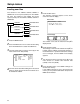
Setup (initial settings) This VTR’s main settings are performed while making selections using a system of menus. If a TV monitor has been connected to the VIDEO OUT 3 connector or SDI OUT 3 connector on the rear panel, the setting menus are displayed on the TV monitor.
Setup menus This VTR can hold five user files, each of which has its own specific menu settings, and one of these files can be selected for use. Changing the file 1 Press the MENU button. the FF button is pressed while holding down 2 When the DIAG button, the next user file is selected; conversely, when the REW button is pressed while holding down the DIAG button, the previous user file is selected.
Setup menus Loading user files The contents of the USER2, USER3, USER4 or USER5 file can be copied (loaded) into the USER1 file. Also, the contents of the USER1 file can be copied (saved) into the USER2, USER3, USER4 or USER5 file. screen and counter display. Menu screen SETUP-MENU Load/save USER 1 the SET button.
Setup menus Saving user files 1 Press the MENU button. the PLAY button. 6 Press The settings of USER1 are saved in the user file the REW button or FF button while holding 2 Press down the DIAG button to select the USER1 file. the search dial to move the cursor (2) on the 3 Turn menu screen to No. A01 (SAVE). SETUP-MENU MENU NO.A00-0000 804 BLANK LINE BLANK A00 LOAD USER2 USER2 2A01 SAVE A02 P.ON LOAD OFF END selected in step 4 and stored in the memory.
Setup menus SYSTEM menu No./Item 00 Description This selects the signal to output from the VIDEO OUT 2 connector. WFM SEL No./Item 14 SCH COARSE 0000 0001 CTL : The CTL signal is output. TC : The TIME CODE signal is output. 0002 VIDEO : The VIDEO OUT signal is output. 0003 RF_L : The PB L RF signal is output. 0004 RF_R : The PB R RF signal is output. 0005 ENV_L : The PB L ENV signal is output. 0006 ENV_R : The PB R ENV signal is output.
Setup menus SYSTEM menu No./Item Description No./Item 18 System phase adjustment. 23 SYS H OFFSET 0000 –3 : –13.4 µsec 0001 –2 : –8.96 µsec 0002 –1 : –4.52 µsec 0003 0 : 0 sec 0004 1 : +4.52 µsec 0005 2 : +8.96 µsec 0006 3 : +13.4 µsec Factory settings will remain unchanged even if an attempt is [525i system] SET UP LEVEL 19 SYS SC/H This sets whether the system phase is to be adjusted by the unit or from the external encoder remote controller. This sets the setup (black) level. Max.
Setup menus USER menu No./Item 000 P-ROLL TIME Description This sets the preroll time. The preroll time can be set from 0 to 15 seconds in 1-second increments. 0000 : 0005 : 0015 001 LOCAL ENA 0s : 5s : 15s When the automatic editing mode [PREVIEW, AUTO EDIT] is set, the unit will not operate if the preroll time is set to 0 seconds. This selects the buttons which can be operated on the front panel when the CONTROL switch has been set to REMOTE. 0000 DIS : No buttons can be operated.
Setup menus USER menu No./Item Description 009 This sets the position of the characters on the horizontal plane for the time code and other CHARA H-POS super displays output to the VIDEO OUT 3/ SDI OUT 3 connector. No./Item 013 0000 MANUAL : The format complies with the setting of setup menu No. 012 (SYS FORMAT) when a DVCPRO cassette is inserted. The format complies to the format recorded on the tape when a DV or DVCAM cassette is inserted.
Setup menus USER menu No./Item 100 SEARCH ENA 101 Description This selects the direct search dial operation. 0000 DIAL : For direct search dial operations. 0001 KEY : Operation is not transferred to the search mode unless the search button is pressed. No./Item 105 AUTO EE SEL SHTL MAX 102 a8.4 : 8.4a normal speed a16 : 16a normal speed a32 : 32a normal speed This sets the maximum speed for FF and REW operations. FF.
Setup menus USER menu No./Item No./Item Description 109 This selects whether to rewind the tape automatically to the tape start when the tape end is detected. AUTO REW 0000 0001 110 OFF : The tape stops at the tape end. ON : The tape is rewound to the tape start. 0000 OFF : The VTR does not stop. 0001 ON : The VTR stops automatically. OThe stop mode concerned is either the stop or the still-picture (SHTL STILL or SLOW STILL) mode depending on the setup menu No.
Setup menus USER menu No./Item 114 REC INH LAMP Description This selects whether to cause the REC INH lamp to flash or light up when the cassette has been set to the accidental erasure prevention status. 0000 LIGHT : The lamp lights up. 0001 FLASH : The lamp flashes. When the REC INH switch is set to ON, the REC INH lamp always lights regardless of the general setting status.
Setup menus USER menu No./Item 200 Description This selects whether two or more VTRs are to be operated in synchronization. PARA RUN No./Item 208 9P SEL 0000 NON : Parity bit is not used. 0001 ODD: An odd number of bits is used for the parity system. 0002 EVEN: An even number of bits is used for the parity system. This selects whether the REMOTE (9P) connector functions when the CONTROL switch has been set to REMOTE. 209 0000 0001 202 OFF : Connector does not function.
Setup menus USER menu No./Item 301 SD955B IN/OUT DEL Description This selects the operation to be performed when an edit point has been set incorrectly (when the OUT point is before the IN point). No./Item 306 EDIT RPLCE2 0000 MANU : Editing is not executed unless the illegal edit point is cleared or set again properly. 0001 AUTO : The edit points already input are automatically cleared.
Setup menus USER menu No./Item 309 EDIT RPLCEC Description The same type of setting as setup menu No. 305. This selects the channel concerned when the CUE edit preset is set in compliance with the ON or OFF presetting for the analog audio signals designated by the controller. 0000 N-DEF : Not set. 0001 CH1 : Compliance with analog CH1 edit preset. 0002 CH2 : Compliance with analog CH2 edit preset. 0003 CH1+2 : Compliance with either analog CH1 or CH2 edit preset. 310 No.
Setup menus USER menu No./Item 400 STILL TIMER Description This selects the time to be taken until the unit goes into the tape protection mode when it is left standing in the stop or search still (JOG/SLOW/SHTL) mode. (Unit: s = second, min = minute) 0000 0001 0002 0003 0004 0005 0006 0007 0008 401 SRC PROTECT 0.5s 5s 10s 20s 30s 40s 50s 1min 2min OSTEP FWD and HALF LOADING are provided in the tape protection mode. Either of these can be set for STOP and SEARCH STILL.
Setup menus USER menu
Setup menus USER menu No./Item 511 VITC OUT
Setup menus USER menu
Setup menus USER menu No./Item 620 ESR MODE
Setup menus USER menu No./Item 623 SETUP 50
Setup menus USER menu
Setup menus USER menu
Setup menus USER menu
Setup menus USER menu
Setup menus USER menu No./Item 800 Description For selecting the mode for recording signals on additional lines. ADD LINE 25 0000 OFF : No signals are recorded on additional lines. 0001 YC422 : The 422 mode signals are recorded on 1 line. 0002 YC411 : The 411 mode signals are recorded on 1 line. 0003 Y1_B/W : Only the Y signal is recorded on 1 line directly. 0004 Y1_BPF : Only the Y signal is recorded on 1 line after it has been separated from the C signal.
Setup menus USER menu No./Item 801 Description For selecting the mode for recording signals on additional lines. ADD LINE 50 0000 OFF : No signals are recorded on additional lines. 0001 YC422 : The 422 mode signals are recorded on 2 lines. 0002 Y4_B/W : Only the Y signal is recorded on 4 lines directly. 0003 Y4_BPF : Only the Y signal is recorded on 4 lines after it has been separated from the C signal. 0004 C4 : Only the C signal is recorded on 4 lines.
Setup menus USER menu No./Item 803 TELETEXT DET Description For selecting the method used to detect the lines in which the teletext signals are to be recorded. 0000 OFF : The teletext signals are not recorded. 0001 AUTO : The teletext signals are automatically detected and recorded. 0002 MANU : The lines in which the teletext signals are to be recorded are selected and set.
Setup menus USER menu